Chrysler Town & Country/Voyager, Dodge Caravan, Plymouth Voyager. Manual - part 161


  Index      Chrysler     Chrysler Town & Country/Voyager, Dodge Caravan, Plymouth Voyager - service repair manual 1992 year


Search            


Content   ..  159  160  161  162   ..


Chrysler Town & Country/Voyager, Dodge Caravan, Plymouth Voyager. Manual - part 161


a soft tool such as a dowel rod, press out the cup and
piston that remain in the wheel cylinder.

(3) Wash wheel cylinder, pistons, and spring in clean

brake fluid or alcohol; (DO NOT USE ANY PETRO-
LEUM BASE SOLVENTS) 
clean thoroughly and
blow dry with compressed air. Inspect cylinder bore
and piston for scoring and pitting. (Do not use a rag as
lint from the rag will stick to bore surfaces.)

Wheel cylinder bores and pistons that are badly

scored or pitted should be replaced. Cylinder walls that
have light scratches, or show signs of corrosion, can
usually be cleaned with crocus cloth, using a circular
motion. Black stains on the cylinder walls are caused
by piston cups and will not impair operation of cylin-
der.

ASSEMBLING WHEEL CYLINDERS

Before assembling the pistons and new cups in the

wheel cylinders, dip them in clean brake fluid. If the
boots are deteriorated, cracked or do not fit tightly on
the pistons or the cylinder casting, install new boots.

(1) Coat cylinder bore with clean brake fluid.
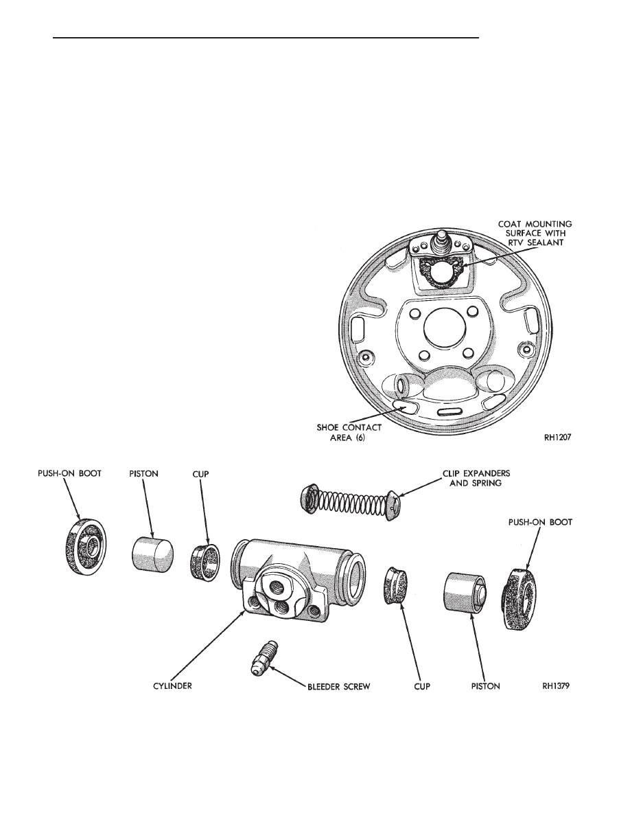
(2) Install expansion spring with cup expanders in

cylinder. Install cups in each end of cylinder with open
end of cups facing each other (Fig. 3).

(3) Install piston in each end of cylinder having the

flat face of each piston contacting the flat face of each
cup, already installed (Fig. 3).

(4) Install a boot over each end of cylinder. Be

careful not to damage boot during installation.

INSTALLING WHEEL CYLINDERS

(1) Apply Mopar

t Gasket In-A-Tube or equivalent

sealant around wheel cylinder mounting surface
(Fig. 4).

(2) Install wheel cylinder onto brake support, and

tighten the wheel cylinder to brake support plate
attaching bolts to 8 N

Im (75 in. lbs.).

(3) Attach hydraulic brake tube to wheel cylinder,

and tighten tube to wheel cylinder fitting to 17 N

Im

(145 in. lbs.).

(4) Install brake shoes on support plate.
(5) Install rear brake drum onto rear hub. Install

rear wheel and tire assembly, tighten wheel stud nuts
to 129 N

Im (95 ft. lbs.).

(6) Adjust the rear brakes, (See Adjusting Service

Brakes) in Service Adjustments section in this group of

the service manual.

(7) Bleed the entire brake system. See (Bleeding

Brake System) in Service Adjustments section in this
group of the service manual.

Fig. 3 Rear Wheel Cylinder

Fig. 4 Apply Sealant on Support Plate

.

BRAKES

5 - 27

HYDRAULIC SYSTEM CONTROL VALVES

INDEX

page

page

ABS Brake Proportioning Valve Operation

. . . . . . . 29

General Information

. . . . . . . . . . . . . . . . . . . . . . . 28

GENERAL INFORMATION

All models have a hydraulic system pressure differ-

ential warning light switch and a height sensing pro-
portioning valve, in the brake system (Figs. 1 and 3).
The switch is attached to the frame rail below the
master cylinder (Fig. 2).

PRESSURE DIFFERENTIAL WARNING LIGHT
SWITCH

The hydraulic brake system on all vehicles is a

diagonally split system. The left front and right rear
brakes are part of one system. The right front and left
rear are part of another. Both systems are routed
through, but hydraulically separated by the Pressure
Differential Switch (Fig. 1). The function of the Pres-
sure Differential Switch is to alert the driver of a

malfunction in the brake system.

If hydraulic pressure is lost in one system, the

warning light switch (Fig. 2) will activate a red light on
the instrument panel, when the brake pedal is de-
pressed. At this point the brakes require service. How-
ever, since the brake systems are split diagonally the
vehicle will retain 50% of its stopping capability in the
event of a failure in either half.

The warning light switch is the latching type. It

will automatically center itself after the repair is
made and the brake pedal is depressed.

The instrument panel bulb can be checked each time

the ignition switch is turned to the start position or the
parking brake is set.

HEIGHT SENSING DUAL PROPORTIONING
UNIT OPERATION

These vehicles use a height sensing proportioning

valve (Fig. 3) in addition to the pressure differential
switch. The height sensing proportioning valve is
mounted on the left rear frame rail forward of the
spring assembly (Fig. 3). An actuator assembly is
connected between the valve lever and a plastic re-
tainer inserted into the actuator bracket.

The height sensing proportioning valve modulates

the pressure to the rear brakes, sensing vehicle load
condition through movement of the actuator bracket.
Optimum front to rear brake balance is maintained
regardless of the vehicle load condition. Under a light
load condition, line pressure to the rear brakes is
minimized. As the load condition increases, so does the
pressure to the rear brakes.

Fig. 1 Pressure Differential Valve And Switch As-

sembly

Fig. 2 Brake Warning Switch Location

5 - 28

BRAKES

.

CAUTION: The use of after market load leveling or
capacity increasing devices are prohibited. Use of air
shock absorbers or helper springs will cause the
valve to inappropriately reduce the rear brake power
potentially resulting in increased stopping distance.

The proportioning valve section operates by trans-

mitting full input pressure to the rear brakes up to a
certain point. Called the split point. Beyond that point
it reduces the amount of pressure increase to the rear
brakes according to a certain ratio.

Thus, on light pedal applications. Approximately

equal brake pressure will be transmitted to the front
and rear brakes. While at higher pressures, the pres-
sure transmitted to the rear brakes will be lower than
to the front brakes. This will prevent premature rear
wheel lock-up and skid.

The height sensing proportioning valve changes the

split point of the valve, based on vehicle rear suspen-
sion height. When the rear height is low, the valve
interprets this as extra load and raises the split point
to allow more rear braking. When the rear suspension
height is high, the split point is lowered and rear
braking reduced.

ABS BRAKE PROPORTIONING VALVE OPERATION

On vehicles using the ABS braking system, screw in

proportioning valves are used in place of the conven-
tional differential pressure/proportioning valve.

Each rear brake circuit has its own screw-in propor-

tioning valve which is attached to the rear brake outlet
ports of the hydraulic assembly. These valves limit
brake pressure to the rear brakes after a certain
pressure is reached. This improves front to rear brake
balance during normal braking.

Screw in proportioning valves can be identified by

the numbers stamped on the body of the valve. The
first digit represents the slope, the second digit repre-
sents the split (cut-in) point, and the arrow represents
the flow direction of the valve. Be sure that the
numbers listed on the replacement valve are the
as on the valve that is being removed. 
See (Fig. 4)
for detail of the valve identification.

Fig. 3 Height Sensing Proportioning Valve Assembly

.

BRAKES

5 - 29

Fig. 4 ABS PROPORTIONING VALVE

IDENTIFICATION

PROPORTIONING VALVE APPLICATIONS

5 - 30

BRAKES

.


Content   ..  159  160  161  162   ..