Chrysler Town & Country/Voyager, Dodge Caravan, Plymouth Voyager. Manual - part 98


  Index      Chrysler     Chrysler Town & Country/Voyager, Dodge Caravan, Plymouth Voyager - service repair manual 1992 year


Search            


Content   ..  96  97  98  99   ..


Chrysler Town & Country/Voyager, Dodge Caravan, Plymouth Voyager. Manual - part 98


ALL WHEEL DRIVE POWER TRANSFER UNIT (P.T.U.)

INDEX

page

page

Fluid Leak Diagnosis

. . . . . . . . . . . . . . . . . . . . . 141

General Information

. . . . . . . . . . . . . . . . . . . . . . 141

Output Flange Shim Selection

. . . . . . . . . . . . . . 150

Power Transfer Unit (P.T.U.)

. . . . . . . . . . . . . . . . 142

Power Transfer Unit End Cover Ball Bearing

. . . . 155

Power Transfer Unit End Cover—Reseal

. . . . . . . 145

Power Transfer Unit Half Shaft Inner Seal

. . . . . . 152

Power Transfer Unit Input Shaft Cover Seal

. . . . 150

Power Transfer Unit Input Shaft End Seal

. . . . . . 153

Power Transfer Unit Input Shaft Seal

. . . . . . . . . 146

Power Transfer Unit Outer Half Shaft Seal

. . . . . 155

Power Transfer Unit Output Seal . . . . . . . . . . . . . 148
Power Transfer Unit Rear Cover O-Ring

. . . . . . . 148

Seal Identification

. . . . . . . . . . . . . . . . . . . . . . . . 141

Transaxle Differential Carrier Seal

. . . . . . . . . . . . 147

GENERAL INFORMATION

The Power Transfer Unit (P.T.U.) is attached to a

modified automatic transaxle case where the right half
shaft extension housing would normally be located.
The Transfer Unit provides the power to the rear
wheels through a hypoid ring gear and pinion set.

The Power Transfer Unit is sealed from the transaxle

and has its own oil sump. The Unit uses SAE 85W-90
gear lubricant and holds 1.15 liters (1.22 quarts).

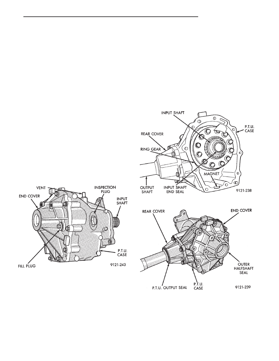
The Power Transfer Unit fill plug is located on the

end cover (Fig. 1). Do not mistake the black plastic
inspection plug located on the P.T.U. case for the
fill plug.

Service of the Power Transfer Unit is limited to the

seals, gaskets and one ball bearing. If the ring gear and
pinion, any tapered roller bearings, case, covers, or
pinion carrier fail the entire unit must be replaced.

SEAL IDENTIFICATION

For accurate seal diagnosis and repair seal name and

location is critical. Refer to figures 1, 2, 3 and 4 for
appropriate seal name and location.

FLUID LEAK DIAGNOSIS

When diagnosing fluid leaks on the Power Transfer

Unit assembly two weep holes are provided to diagnose
certain seal leaks. These holes are located on the
bottom side of the assembly (Fig. 5).

If fluid leak is detected from either weep hole, seal

replacement is necessary. Do not attempt to repair

Fig. 1 Fill Plug Location

Fig. 1 Seal Location

Fig. 2 Seal Location

.

TRANSAXLE

21 - 141

the leak by sealing weep holes, they must be kept
clear of sealants for proper seal operation.

If fluid is leaking from weep hole ‘‘A’’ (Fig. 5) the type

of fluid leaking will determine which seal needs to be
replaced. If the fluid leaking is red in color (transmis-

sion fluid) this indicates that the Transmission differ-
ential carrier seal should be replaced. If the fluid
leaking is light brown (gear lube) this indicates that
the Power Transfer Unit input seal should be replaced.
For replacement of these seals refer to Power Transfer
Unit Service Procedures.

If fluid is leaking from weep hole ‘‘B’’ (Fig. 5) the type

of fluid leaking will determine which seal is leaking. If
the fluid leaking is red in color (transmission fluid) this
indicates that the input shaft end seal should be
replaced. If the fluid leaking is light brown (gear lube)
this indicates that the half shaft inner seal and P.T.U.
input shaft cover seal should be replaced. For replace-
ment of these seals refer to Power Transfer Unit
Service Procedures.

Before condemning any seal or gasket be sure that

the rear rocker arm cover on the engine is not the cause
of the oil leak. Oil leaking from the rocker arm cover is
easily mistaken for a leaking Power Transfer Unit.

POWER TRANSFER UNIT (P.T.U.)

REMOVAL AND INSTALLATION

(1) Raise vehicle and remove front wheels.
(2) Remove propeller shaft assembly.

Fig. 3 Seal Location

Fig. 4 Seal Location

Fig. 5 Weep Hole Locations

Fig. 1 Remove Cross Member Bridge Bolts

21 - 142

TRANSAXLE

.

Fig. 2 Remove Power Steering Hose Bracket

Fig. 3 Secure Rack and Pinion to Frame Rail

Fig. 4 Remove Ball Joint Bolt (Right and Left Side)

Fig. 5 Remove Lower Bobble Strut Bolt

.

TRANSAXLE

21 - 143

CAUTION: A certain amount of oil will drain out of the
transaxle when the drive shaft is removed.

Remove right front drive shaft. Refer to ‘‘Sus-

pension, Group 2’’ to remove or install wheel hub
nut and right drive shaft.

Fig. 6 Support Crossmember with Transmission

Jack

Fig. 7 Remove Front Suspension Crossmember

Fasteners

Fig. 8 Lower Crossmember Assembly and Remove

Fig. 9 Remove P.T.U Support Bracket and Bobble

Strut Assembly

Fig. 10 Remove Rear P.T.U Brace Bolts

21 - 144

TRANSAXLE

.


Content   ..  96  97  98  99   ..