Chrysler Town & Country/Voyager, Dodge Caravan, Plymouth Voyager. Manual - part 16


  Index      Chrysler     Chrysler Town & Country/Voyager, Dodge Caravan, Plymouth Voyager - service repair manual 1992 year


Search            


Content   ..  14  15  16  17   ..


Chrysler Town & Country/Voyager, Dodge Caravan, Plymouth Voyager. Manual - part 16


INSTALLATION

(1) Install inlet hose on fuel tube and tighten new

clamp to 1 N

Im (10 in. lbs.) torque.

(2) Install outlet hose on filter outlet fitting and

torque new clamp to 1 N

Im (10 in. lbs.).

(3) Position filter assembly on rail and tighten

mounting screw to 8 N

Im (75 in. lbs.) torque.

FUEL FILTER—ALL WHEEL DRIVE

REMOVAL

WARNING: FUEL SYSTEM PRESSURE MUST BE RE-
LEASED BEFORE THE FUEL FILTER IS REMOVED.

(1) Perform Fuel System Pressure Release proce-

dure.

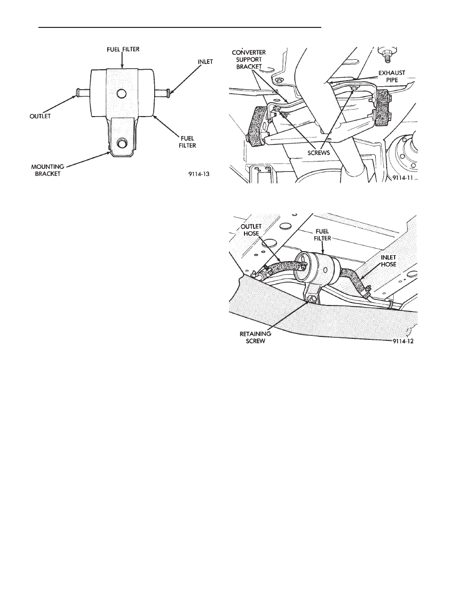
(2) Remove converter support bracket (Fig. 19).
(3) Remove exhaust pipe heat shield.
(4) Loosen outlet and inlet hose clamps on filter (Fig.

20).

CAUTION: Wrap shop towels around hoses to catch
any gasoline spillage.

(5) Remove filter retaining screw and remove filter

assembly from rail.

(6) Remove hoses from fuel filter. Discard clamps.

INSTALLATION

(1) Loose install inlet and outlet fuel hoses to fuel

filter.

(2) Position filter assembly on rail and tighten

mounting screw to 8 N

Im (75 in.lbs.) torque.

(3) Tighten new fuel hose clamps to 1 N

Im (10 in.

lbs.) torque.

(4) Install exhaust pipe heat shield.
(5) Install exhaust pipe support bracket.

CHASSIS FUEL TUBES

Fuel system component locations and chassis fuel

tube routings are shown in Fig. 21.

Fig. 18 Fuel Filter—Front Wheel Drive

Fig. 20 Fuel Filter—All Wheel Drive

Fig. 19 Support Bracket—All Wheel Drive

.

FUEL SYSTEM

14 - 11

Fig.

21

Fuel

T

ank,

Filter

,

and

Chassis

Line

Routing

14 - 12

FUEL SYSTEM

.

FUEL TANK

INDEX

page

page

Fuel Pump Module—All Wheel Drive

. . . . . . . . . . 18

Fuel Pump/Level Unit—Front Wheel Drive

. . . . . . 18

Fuel System Pressure Release Procedure

. . . . . . 13

Fuel Tank Pressure Relief/Rollover Valve

—All Wheel Drive

. . . . . . . . . . . . . . . . . . . . . . . 19

Fuel Tank Pressure Relief/Rollover Valve—Front Wheel

Drive

. . . . . . . . . . . . . . . . . . . . . . . . . . . . . . . . 18

Fuel Tank—All Wheel Drive

. . . . . . . . . . . . . . . . . 16

Fuel Tank—Front Wheel Drive

. . . . . . . . . . . . . . . 14

General Information

. . . . . . . . . . . . . . . . . . . . . . . 13

No-Lead Fuel Tank Filler Tube

. . . . . . . . . . . . . . . 13

Pressure-Vacuum Filler Cap—Front Wheel Drive . . 13

GENERAL INFORMATION

The fuel tanks of all Chrysler Motors built vehicles

are equipped with fuel and vapor controls that allow
the vehicle to pass a full 360° rollover without fuel
leakage.

Both front wheel drive and all wheel drive fuel

delivery

systems

contain

a

fuel

tank

pressure

relief/rollover valve. The valve is mounted on the top of
the fuel tank on front wheel drive vehicles and on top of
the fuel pump module on all wheel drive vehicles. The
valve functions as a pressure relief valve while the
vehicle is upright, but contains a check valve that
prevents fuel from escaping from the fuel tank when
the vehicle is turned over.

The fuel filler cap also acts as a pressure/vacuum

valve. When air pressure inside the fuel tank gets too
high or too low, the fuel filler cap opens to relieve the
difference in pressure.

An evaporation control system restricts fuel evapo-

ration into the atmosphere and reduces unburned
hydrocarbons. Vapors from the fuel tank are collected
in a charcoal filled canister. The vapors are held in the
canister until the engine is operating. When the engine
is running, the vapors are drawn through the intake
manifold into the combustion chambers.

NO-LEAD FUEL TANK FILLER TUBE

All catalyst equipped vehicles have a special fuel

tank filler tube. The fuel filler opening is smaller in
diameter than those used for non-catalyst vehicles.
Gasoline station pumps for leaded and unleaded fuel
have different size nozzles. The unleaded pump nozzle
is smaller than the leaded pump nozzle. The fuel tank
filler neck opening contains a deflector that the smaller
unleaded nozzle pushes back upon entering the filler
neck. The deflector prevents the larger diameter
leaded fuel nozzles from entering the filler neck. It also
deflects fuel away from the filler neck if filling of the
tank with leaded fuel is attempted.

The fuel filler tube on these models is equipped with

a one way ball check valve. The valve prevents fuel
splash back when filling the tank.

As a reminder, a label that reads UNLEADED

FUEL ONLY is attached to the instrument panel
under the fuel gauge. A similar label is located near the
fuel tank filler.

PRESSURE-VACUUM FILLER CAP—FRONT WHEEL
DRIVE

The loss of any fuel or vapor out of the filler neck is

prevented by the use of a safety filler cap. The cap will
release pressure only under significant pressure of 10.9
to 13.45 kPa (1.58 to 1.95 psi). The vacuum release for
all gas caps is between .97 and 2.0 kPa (.14 and .29 psi).
The cap must be replaced by a similar unit if replace-
ment is necessary.

WARNING: REMOVE FILLER CAP TO RELIEVE TANK
PRESSURE BEFORE REMOVING OR REPAIRING
FUEL SYSTEM COMPONENTS.

FUEL SYSTEM PRESSURE RELEASE PROCEDURE

The 2.5L engine fuel system is under a constant

pressure of approximately 270 kPa (39 psi). The fuel
systems of 3.0L and 3.3L engines are under a constant
pressure of approximately 330 kPa (48 psi). Fuel sys-
tem pressure must be released before servicing any
fuel system component.

(1) Remove fuel filler cap to release fuel tank pres-

sure.

(2) Disconnect injector wiring harness from engine

or main harness.

FUEL TANK CAPACITIES

.

FUEL SYSTEM

14 - 13

(3) Connect a jumper wire from terminal Number 1

(ground) of the injector harness (Fig. 1) to engine
ground.

(4) Connect one end of a jumper wire to terminal

Number 2 (positive) of the injector harness (Fig. 1).
Connect the other end to the positive post of the
battery for no longer than 5 seconds. This releases
system pressure.

(5) Remove jumper wires.
(6) Continue fuel system service.

FUEL TANK—FRONT WHEEL DRIVE

DRAINING FUEL TANK

(1) Remove fuel filler cap and perform Fuel System

Pressure Release procedure.

(2) Disconnect battery ground cable.
(3) Raise vehicle on hoist.
(4) Remove rubber cap from drain tube. The tube is

located on rear of fuel tank. Connect a portable holding
tank to the drain tube (Fig. 2).

(5) Drain fuel tank dry into holding tank or a prop-

erly labeled gasoline safety container.

FUEL TANK REMOVAL—FRONT WHEEL DRIVE

(1) Raise vehicle on hoist.
(2) Drain fuel tank. Refer to Draining Fuel Tank.
(3) Remove fuel filler cap before disconnecting any

lines.

(4) Remove screws that hold filler tube to inner and

outer quarter panel (Fig. 3).

Fig. 1 Injector Harness Connectors

Fig. 2 Fuel Drain Tube—Front Wheel Drive

14 - 14

FUEL SYSTEM

.


Content   ..  14  15  16  17   ..