Index Chrysler Chrysler Le Baron, Dodge Dynasty, Plymouth Acclaim - service repair manual 1993 year
Search
Content .. 588 589 590 591 ..
Chrysler Le Baron, Dodge Dynasty, Plymouth Acclaim. Manual - part 590
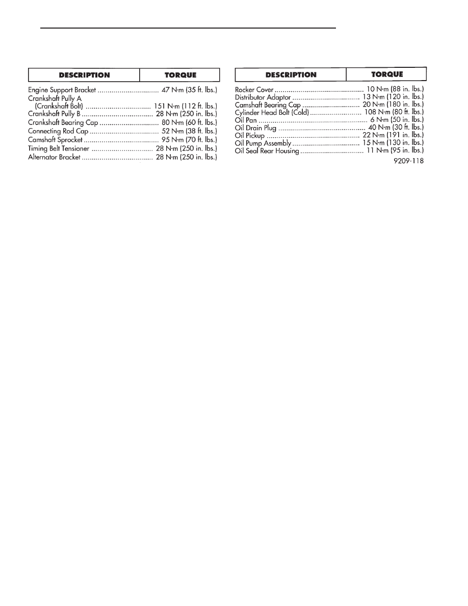
TORQUE
Ä
3.0L ENGINE
9 - 97