Chrysler Le Baron, Dodge Dynasty, Plymouth Acclaim. Manual - part 363
When a fusible link blows it is important to find
out what the problem is. They are placed in the sys-
tem for protection against shorts. Which can be
caused by a component failure or wiring failures. Do
not just replace the fusible link to correct the
problem.
When diagnosing a faulty fusible link it is impor-
tant to check the wire carefully. In some instances
the link may be blown and it will not show through
the insulation, the wire should be checked over its
entire length for internal breaks.
(1) Disconnect battery negative cable.
(2) Cut out the blown portion of the fusible link.
(3) Strip 1 inch of insulation from each end of the
existing fusible link.
(4) Place a piece of heat shrink tubing over one
side of the fusible link. Make sure the tubing will be
long enough to cover and seal the entire repair area.
(5) Cut a replacement piece of fusible link approx-
imately two inches longer than the piece removed.
(6) Remove one inch of insulation from each end of
the replacement fusible link.
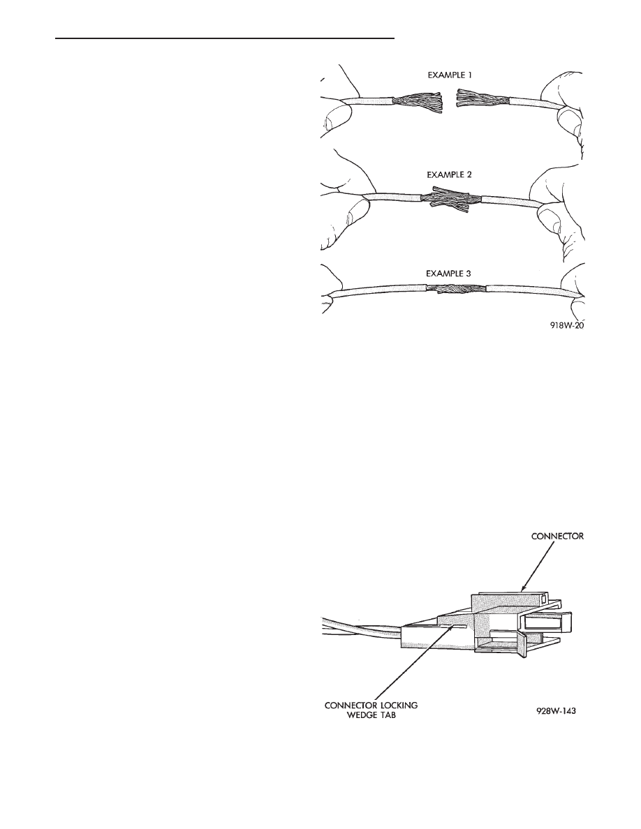
(7) Spread the strands of wire apart on each of the
exposed wires (Fig. 11 example 1).
(8) Push the two ends of the wire together until
the strands of wire are close to the insulation (Fig.
11 example 2).
(9) Twist the wires together (Fig. 11 example 3).
(10) Solder the wires together using rosin core type
solder only. Do not use acid core type solder.
(11) Center the heat shrink tubing over the joint
and heat using a heat gun. Heat the joint until the
tubing is tightly sealed and sealant comes out of both
ends of the tubing.
(12) Secure the fusible link to the existing ones to
prevent chafing or damage to the insulation.
(13) Connect battery and test all affected systems.
WIRING REPAIR
When replacing or repairing a wire, it is important
that the correct gauge be used as shown in the wir-
ing diagrams. The wires must also be held securely
in place to prevent damage to the insulation.
(1) Disconnect battery negative cable.
(2) Remove 1 inch of insulation from each end the
wire.
(3) Place a piece of heat shrink tubing over one
side of the wire. Make sure the tubing will be long
enough to cover and seal the entire repair area.
(4) Spread the strands of the wire apart on each
part of the exposed wires (Fig. 11 example 1).
(5) Push the two ends of wire together until the
strands of wire are close to the insulation (Fig. 11 ex-
ample 2).
(6) Twist the wires together (Fig. 11 example 3).
(7) Solder the connection together using rosin core
type solder only. Do not use acid core solder.
(8) Center the heat shrink tubing over the joint
and heat using a heat gun. Heat the joint until the
tubing is tightly sealed and sealant comes out of both
ends of the tubing.
(9) Secure the wire to the existing ones to prevent
chafing or damage to the insulation.
(10) Connect battery and test all affected systems.
CONNECTOR REPLACEMENT
(1) Disconnect battery.
(2) Disconnect the connector that is to be repaired
from its mating half.
(3) Remove connector locking wedge (Fig. 12).
(4) Position the connector locking finger away from
the terminal. Pull on the wire to remove the termi-
nal from the connector (Fig. 13).
Fig. 11 Wire Repair
Fig. 12 Connector Locking Wedge Tab
Ä
GENERAL INFORMATION
8W - 5