Chrysler Le Baron, Dodge Dynasty, Plymouth Acclaim. Manual - part 357


  Index      Chrysler     Chrysler Le Baron, Dodge Dynasty, Plymouth Acclaim - service repair manual 1993 year


Search            


Content   ..  355  356  357  358   ..


Chrysler Le Baron, Dodge Dynasty, Plymouth Acclaim. Manual - part 357


(4) To remove motor from regulator, grip motor

housing and pull motor towards inner or outer panel,
depending on regulator type. Some rocking or twist-
ing action may be necessary to disengage motor from
regulator.

WARNING:DO NOT HAVE ANY HANDS OR FIN-
GERS IN SECTOR GEAR AREA WHERE THEY CAN
BE PINCHED BY SMALL MOVEMENTS OF REGULA-
TOR LINKAGE.

INSTALLATION

New motor gearbox retaining screw holes are not

threaded. It may be desirable to tap holes before at-
tempting assembly.

(1) Install new motor on regulator by positioning

motor gearbox so that it engages regulator sector
teeth.

(2) Position motor so that center post gearbox fits

into its pilot hole in plate. A slight rotational or
rocking movement may be necessary to bring three
motor gearbox screw holes into proper position.

(3) Install three gearbox screws and one tie down

bracket screw, if applicable. Tighten to 5 to 7 N

Im

(50 to 60 in. lbs.) torque.

(4) Connect pigtail wiring harness connector.
(5) Remove window block.
(6) Actuate regulator with switch to verify satis-

factory operation.

BENCH REPAIR OF REGULATOR AND MOTOR
CONVENTIONAL REGULATORS

To repair or inspect the entire electric window reg-

ulator, remove from the door as follows:

REMOVAL

(1) Disconnect wiring connector from motor.
(2) Hold glass in the up position.
(3) Remove rivets and/or screws that hold regula-

tor and motor to inner door panel.

(4) Maneuver regulator assembly by hand to disen-

gage the drive arm slider from the glass lift channel.
Remove from door.

REPAIR

If entire regulator is not being replaced, repair as

follows:

WARNING:REMOVE COUNTER BALANCE SPRING
BEFORE THE MOTOR IS REMOVED. IF IT IS NOT,
THE SPRING TENSION WILL CAUSE THE REGULA-
TOR ARMS TO CLOSE AS SOON AS THE MOTOR
IS REMOVED AND COULD SERIOUSLY INJURE
YOUR FINGERS 
.

(1) Remove regulator as described above.
(2) Secure regulator in vise to prevent sector gear

from rotating.

(3) Remove counter balance spring.
(4) Remove three motor attaching screws and re-

move motor.

(5) Inspect regulator for:

(a) Sector gear teeth must not be broken or se-

verely worn.

(b) All rivets and sliders must be securely at-

tached.

(c) Parts must not be bent or cracked.
(d) Sector gear must rotate freely.
(e) Perform window lift motor test as described

above.

INSTALLATION

(1) Install motor and attach with three motor at-

taching screws. If installation of new motor is neces-
sary, it may be desirable to tap motor retaining
screw holes.

(2) Install counter balance spring.
(3) Replace regulator in door by reversing Removal

steps 1, 2 and 3.

(4) Regulators may be secured to door panel using

rivets or 1/4-20 X 1/2 screws and nuts.

MOTOR REPLACEMENT—FLEX DRIVE
REGULATORS

REMOVAL

(1) Raise or lower window to the proper access hole

position and remove screw that attaches the flex rack
to the drive arm (Fig. 10). Hold the glass in that po-
sition.

(2) Remove

the

regulator

attaching

rivets

by

knocking out the rivet center mandrel and drilling

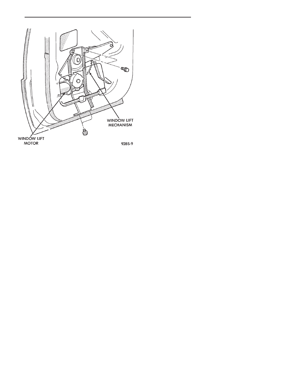
Fig. 9 Rear Door Power Window—AC, and AY Body

Ä

POWER WINDOWS

8S - 5

rivet with a 1/4 inch diameter drill. Remove retain-
ing screws if necessary (Fig. 11 through 14).

(3) Maneuver the motor end of the flex drive reg-

ulator outside of the large inside panel access hole
and rotate regulator out of door.

(4) If the window motor cannot be actuated and is

stuck or frozen in any position other than at the ac-
cess hole, the removal procedure is as follows:

(a) Remove the regulator attaching rivets by

knocking out the rivet center mandrel and drilling
the rivets with a 1/4 inch diameter drill. Remove
retaining screws if necessary.

Fig. 10 Window Regulator Flex Rack to Drive Arm

Fig. 11 Flex Drive Window Regulator Rear Door—AP

Body

Fig. 12 Flex Drive Window Regulator Front

Door—AG Body

Fig. 13 Door Power Window—AG Body

8S - 6

POWER WINDOWS

Ä

(b) Manually lift the window upward with the

unriveted flex drive electric regulator still attached
until the screw can be removed. If more access is
needed, remove the two screws that hold the
T-track to the motor gearbox. This will allow re-
moval of the motor from the T-track.
(5) Remove two screws that fasten the motor gear-

box to the metal T-track.

(6) Perform bench test.

BENCH TEST

(1) Connect positive (+) lead from test battery to

either of the two motor terminals.

(2) Connect negative (-) lead from test battery to

remaining motor terminal.

(3) The motor will now rotate in one direction.
(4) Reverse the battery leads and the motor should

now rotate in the opposite direction.

(5) If the motor does not rotate in both directions,

replace the motor.

INSTALLATION

(1) Install new motor on T-track using No. 8-32 X

1/2 screws tighten to 4 N

Im (40 in. lbs.) torque.

(2) Feed top of T- track into access hole and point

and rotate it towards the hinge pillar until regulator
motor is approximately horizontal. Then rotate regu-
lator in the opposite direction about a 1/4 turn and
line up bracket tab to inner panel slot.

(3) Fasten regulator with the rivet sequence shown

in (Figs. 10 and 11).

(4) Actuate the motor until the flex rack is visible

within the access slot. Attach the window and drive

arm assembly to the flex rack with the screws.
Tighten screws to 4 N

Im (40 in. lbs.) torque.

POWER WINDOW CABLE HOUSING/MOTOR
REPLACEMENT—AC and AY Bodies

WARNING: REMOVAL OF THE WINDOW LIFT MO-
TOR FROM THE REGULATOR WILL CAUSE THE
ASSIST SPRING TO UNWIND RAPIDLY WITH THE
POTENTIAL OF CAUSING PHYSICAL INJURY. IF
THE WINDOW LIFT MOTOR REQUIRES REPLACE-
MENT, SEE REGULATOR REPLACE CABLE AND
DRUM IN THIS GROUP OF THIS MANUAL.

(1) Remove front door trim panel. Refer to group

23, Body.

(2) Disconnect window lift plate from glass (Fig.

15).

(3) Disconnect window track from door.
(4) Disconnect window lift motor and drive cables.
(5) Disconnect electrical connections.
(6) Carefully remove window track, cables and lift

motor assembly from door.

(7) For installation reverse above procedures.

MOTOR REPLACEMENT

(1) Refer to Front Door Window Regulator for re-

moval.

(2) The door glass must be in the down position.
(3) Tape glass to door frame to hold glass in the up

position.

(4) If the window is not in the full up position, re-

move only the motor from the door.

(5) Remove nuts from motor and cable housing

(Fig. 16).

(6) Make sure motor is facing you before separat-

ing motor from housing.

(7) Using a flat tool slowly separate motor from

housing, making sure the cable drum under the mo-
tor stays in cable housing. When motor is fully sep-
arated the assist spring will be completely unwound
(Fig. 17).

(8) Remove assist spring by releasing the tabs on

the opposite sides of the spring, do not remove spring
from its case (Fig. 18).

Fig. 14 Rear Door Power Window—AP Body

ART: 928s-3; SIZE (1) = 1-3/4h x 3-1/2w

Fig. 15 Cable and Housing/Motor

Ä

POWER WINDOWS

8S - 7

INSTALLATION

(1) Install motor into housing with one stud and in

center of housing to secure motor to housing.

(2) Before installing new spring, power the motor

into the full-up position.

(3) Replace assist spring on cable housing. Wind

spring counter clockwise 3 1/2 turns on the left door.
The right door, wind spring clockwise 3 1/2 turns
(Fig. 19).

(4) Install the other two studs and nuts and

tighten to 4 to 5 M

Im (35 to 45 in. lbs.) torque.

(5) Inspect that cables are not twisted prior to in-

stalling motor and housing into door.

QUARTER WINDOW REPLACEMENT—AJ BODY

For steps (1) through (5) refer to Group 23, Body,

for complete procedures.

(1) Remove the folding top sling well assembly.
(2) Remove the quarter trim upper moldings.
(3) Remove the cowl trim and scuff plate panels.
(4) Remove the rear seat cushion.
(5) Remove the quarter trim and rear seat back as-

sembly.

(6) Remove quarter windows assembly (Fig. 20).

Fig. 16 Separating Motor from Housing

Fig. 17 Cable/Drum and Motor

Fig. 18 Assist Spring Cover

Fig. 19 Wind Assist Spring Cover

Fig. 20 Power Quarter Window—AJ Body

8S - 8

POWER WINDOWS

Ä


Content   ..  355  356  357  358   ..