Chrysler Le Baron, Dodge Dynasty, Plymouth Acclaim. Manual - part 327
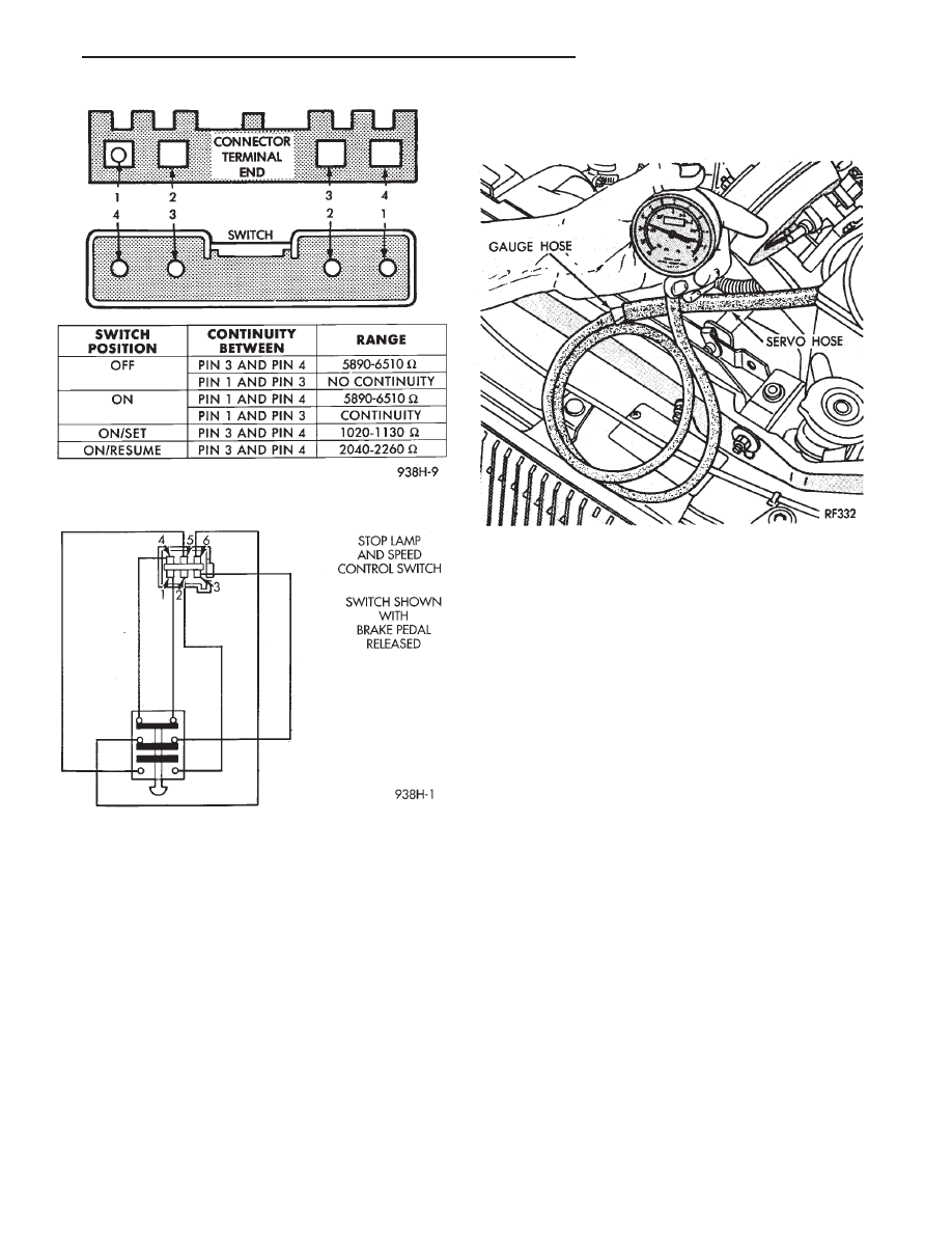
(a) With brake pedal released, there should be
continuity:
• Between pin 1 and pin 4
• Between pin 3 and pin 6
• No continuity between pin 2 and pin 5
(b) With brake pedal depressed, there should be
no continuity:
• Between pin 1 and pin 4
• Between pin 3 and pin 6
• Continuity between pin 2 and pin 5
(2) If the above results are not obtained, the stop
lamp switch is defective or out of adjustment.
(3) Stop lamp switch adjustment is detailed in
Group 5, Brakes.
VACUUM SUPPLY TEST
(1) Disconnect vacuum hose at the servo and in-
stall a vacuum gauge in the hose (Fig. 17).
(2) Start engine and observe gauge at idle. Vac-
uum gauge should read at least ten inches of mer-
cury. Shut off engine, the vacuum should continue to
hold 10 inches of mercury.
(3) If vacuum does not meet this requirement,
check and correct the following vacuum leaks:
• Vacuum lines
• Check valve
• Vacuum reservoir
• Servo, refer to Servo Vacuum Test
• Poor engine performance
SERVO VACUUM TEST
(1) Remove the vehicle speed control cable at the
throttle body end.
(2) Disconnect the 4-way electrical connector and
the vacuum harness at the servo (Refer to Fig. 12).
(3) Connect battery voltage to pin 2 of the servo.
(4) Ground the remaining three servo pins 1, 3 and
4.
(5) Connect a hand held vacuum pump to the servo
vacuum nipple and apply 10 to 15 inches of vacuum.
(6) The cable should pull in and hold for as long as
vacuum is applied.
SERVO UNIT
REMOVAL
(1) Remove two nuts attaching vehicle speed con-
trol cable and mounting bracket to servo.
(2) Remove
screws
attaching
servo
mounting
bracket.
(3) Remove servo mounting bracket.
Fig. 15 Vehicle Speed Control Switch Continuity
Fig. 16 Stop Lamp and Vehicle Speed Control
Switch Wiring
Fig. 17 Vacuum Gauge Test
Ä
VEHICLE SPEED CONTROL
8H - 9