Chrysler Le Baron, Dodge Dynasty, Plymouth Acclaim. Manual - part 238


  Index      Chrysler     Chrysler Le Baron, Dodge Dynasty, Plymouth Acclaim - service repair manual 1993 year


Search            


Content   ..  236  237  238  239   ..


Chrysler Le Baron, Dodge Dynasty, Plymouth Acclaim. Manual - part 238


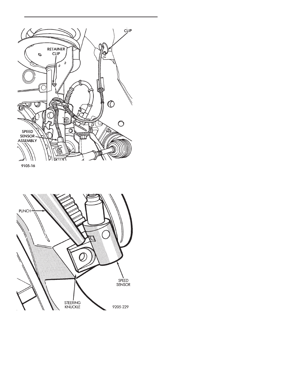
(Fig. 5), rocking the sensor side to side until free. DO
NOT USE PLIERS ON SENSOR HEAD.

INSTALLATION

(1) Connect the wheel speed sensor cable connec-

tor, to the vehicle wiring harness.

(2) Push sensor assembly grommet into hole in

fender shield. Install clip and screw (Fig. 4). Torque
screw to 4 N

Im (35 in. lbs.).

(3) Install speed sensor cable grommets in bracket

on strut damper (Fig. 4).

(4) Install speed sensor cable routing tube to fender

well (Fig. 4). Torque both screws to 4 N

Im (35 in. lbs.).

(5) Coat the speed sensor with High Temperature

Multi-purpose E.P. Grease before installing into the
steering knuckle. Install speed sensor attaching screw
and tighten to 7 N

Im (60 in. lbs.)

CAUTION: Proper installation of wheel speed sensor
cables is critical to continued system operation. Be
sure that cables are routed correctly and installed in
all retainers. Failure to properly route and install
cables in retainers, as shown in this section. May
result in contact with moving parts and/or over ex-
tension of cables, resulting in an open circuit.

REAR WHEEL SPEED SENSOR (FIGS. 6 AND 8)

REMOVAL

(1) Raise vehicle and remove wheel and tire assem-

bly.

(2) Remove sensor assembly grommet from under-

body and pull harness through hole in underbody.

(3) Unplug connector from harness.
(4) Remove sensor grommet bracket screw from

body hose bracket, just forward of trailing arm bush-
ing.

(5) Remove sensor assembly clip, located on the

inboard side of trailing arm.

(6) Remove sensor wire fastener from rear brake

hose bracket.

(7) Remove outboard sensor assembly retainer nut.
(8) Remove sensor head screw.
(9) Carefully, remove sensor head from adapter as-

sembly. If the sensor has seized, due to corrosion, DO
NOT USE PLIERS ON SENSOR HEAD. Use a ham-
mer and a punch (Fig. 7) and tap edge of sensor ear,
rocking the sensor side to side until free.

INSTALLATION

Installation is reverse order of removal. Be sure to

coat sensor with High Temperature Multi-purpose E.P.
Grease

before

installing

into

adapter

assembly.

Tighten screw to 7 N

Im (60 in. lbs.) torque. Avoid

getting grease on the pickup area of the speed sensor
assembly.

Fig. 4 Front Wheel Speed Sensor Routing

Fig. 5 Removing Speed Sensor (Typical)

Ä

ANTI-LOCK 10 BRAKE SYSTEM

5 - 105

DUAL FUNCTION PRESSURE SWITCH

REMOVE

WARNING: FAILURE TO DE-PRESSURIZE THE HY-
DRAULIC ACCUMULATOR PRIOR TO REMOVING
DUAL FUNCTION PRESSURE SWITCH. WILL RESULT
IN

PERSONAL

INJURY

AND/OR

DAMAGE

TO

PAINTED SURFACES OF THE VEHICLE.

CAUTION: THOROUGHLY CLEAN THE BOTTOM OF
THE HYDRAULIC ASSEMBLY IN THE AREA OF THE
DUAL FUNCTION PRESSURE SWITCH, BEFORE RE-
MOVING THE SWITCH FROM HYDRAULIC ASSEM-
BLY. USE MOPAR BRAKE PARTS CLEANER OR AN
EQUIVALENT. EXTREME CARE MUST BE USED SO
NO DIRT IS ALLOWED TO ENTER THE HYDRAULIC
ASSEMBLY THROUGH WHERE THE DUAL FUNC-
TION PRESSURE SWITCH IS MOUNTED. ANY DIRT
ENTERING HYDRAULIC ASSEMBLY MAY PLUG IN-
TERNAL PASSAGES CAUSING A HYDRAULIC AS-
SEMBLY FAILURE.

(1) Fully de-pressurize the hydraulic accumulator by

pumping brake pedal a minimum of 40 times. Use
procedure described in De-Pressurizing Hydraulic Ac-
cumulator listed earlier in this section.

(2) Raise vehicle See Hoisting, Group 0.
(3) From under vehicle, disconnect wiring harness

connectors from dual function pressure switch and
boost pressure transducer (Fig. 9) on the bottom of
hydraulic assembly.

WARNING: WEAR EYE PROTECTION WHEN PER-
FORMING THE FOLLOWING PROCEDURE. SERIOUS
EYE INJURY CAN RESULT FROM BRAKE FLUID
CONTACTING THE EYES.

(4)

Be sure that the hydraulic system is de-

pressurized. Remove the dual function pressure
switch from the hydraulic assembly using Socket,
Special Tool 6607 (Fig. 10). Access to the switch is from
under the vehicle using a long extension.

Fig. 6 Rear Wheel Speed Sensor Routing at Trailing Arm

Fig. 7 Removing Speed Sensor (Typical)

5 - 106

ANTI-LOCK 10 BRAKE SYSTEM

Ä

INSTALL

CAUTION: Be sure that the dual function pressure
switch is thoroughly cleaned using Mopar Brake
Parts Cleaner or an equivalent before installing it
into the hydraulic assembly. Wet the O-ring seals
on the switch with fresh clean brake fluid before in-
stalling it into the hydraulic assembly.

Fig. 8 Body Routing of Rear Speed Sensor Wiring

Fig. 9 Dual Function Pressure Switch And Pressure

Transducer Wiring

Fig. 10 Dual Function Pressure Switch Remove/

Install

Ä

ANTI-LOCK 10 BRAKE SYSTEM

5 - 107

CAUTION: Do not insert dual function pressure
switch into hydraulic assembly using the socket
and ratchet. Cross threading of the switch may oc-
cur.

(1) Install the dual function pressure switch into

the hydraulic assembly by hand until the O-ring
seals are seated.

(2) Using Socket, Special Tool 6607, (Fig. 10)

torque the dual function pressure switch into the hy-
draulic assembly to 12 N

Im (9 ft. lbs.).

(3) Connect the wiring harness connectors (Fig. 9)

onto the dual function pressure switch and the boost
pressure transducer. Be sure the locking tabs on the
connectors are fully engaged on the switches.

(4) Lower the vehicle.
(5) Turn the ignition switch to the on position and

let the system pressurize. Check for any leaks at the
dual function pressure switch.

(6) Fully de-pressurize the hydraulic assembly a

second time. This will purge any air out that may
have entered hydraulic assembly when the switch
was removed. Turn the ignition switch to the on po-
sition and let the system pressurize again.

(7) Road test vehicle to insure that the brake sys-

tem is performing correctly.

PRIMARY PRESSURE TRANSDUCER

REMOVE

WARNING: FAILURE TO FULLY DE-PRESSURIZE
THE HYDRAULIC BLADDER ACCUMULATOR PRIOR
TO

REMOVING

PRIMARY

PRESSURE

TRANS-

DUCER.

WILL

RESULT

IN

PERSONAL

INJURY

AND/OR DAMAGE TO PAINTED SURFACES OF THE
VEHICLE.

To remove primary pressure transducer (Fig. 11),

from hydraulic assembly, removal of hydraulic as-
sembly from vehicle is not required.

(1) Fully de-pressurize the hydraulic accumulator

by pumping brake pedal a minimum of 40 times. Use
procedure described in De-Pressurizing Hydraulic Ac-
cumulator listed earlier in this section.

(2) Remove as much brake fluid as possible from

the brake fluid reservoir, using a syringe or equiva-
lent method.

(3) Using oil filter band wrench, Special Tool

C-4065 or equivalent, (Fig. 12) loosen bladder accu-
mulator. Then remove bladder accumulator and
brake fluid spray shield from hydraulic assembly.

(4) Remove high pressure banjo fitting (Fig. 13)

from hydraulic assembly.

(5) Using needle nose pliers, remove the 3 fluid

reservoir retaining pins from the hydraulic assembly
(Fig. 14). Compress barb on opposite side of retaining
pin, to prevent pin from breaking.

CAUTION: Be extremely careful during the following
procedure to avoid damaging or puncturing brake
fluid reservoir during its removal.

(6) Remove brake fluid reservoir from hydraulic

assembly by carefully prying between reservoir and
hydraulic assembly using a blunt pry bar (Fig. 15).
Use a rocking motion to help disengage reservoir
from grommets while prying.

(7) Remove brake fluid level sensor from reservoir

and remove fluid reservoir from vehicle.

(8) Remove hydraulic assembly wiring harness

connector from the primary pressure transducer (Fig.
16).

Fig. 11 Primary Pressure Transducer Location On

Hydraulic Assembly

Fig. 12 Removing Bladder Accumulator

5 - 108

ANTI-LOCK 10 BRAKE SYSTEM

Ä


Content   ..  236  237  238  239   ..