Chrysler Le Baron, Dodge Dynasty, Plymouth Acclaim. Manual - part 164
OVERHEAD CONSOLE
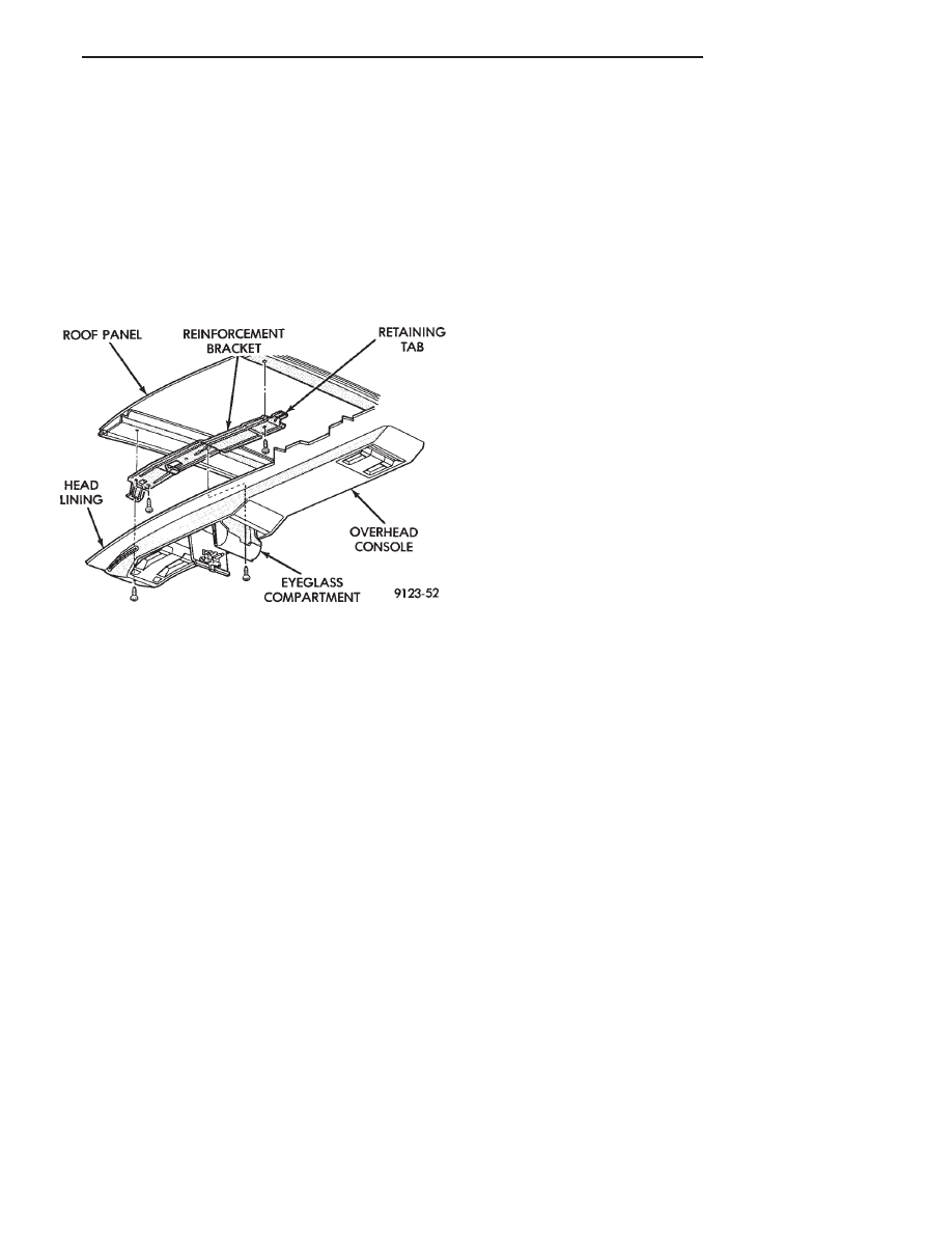
REMOVAL (FIG. 33)
(1) Remove screws holding overhead console to re-
inforcement bracket.
(2) Slide overhead console rearward to separate re-
inforcement bracket retainer tab from console.
(3) Lower console from roof and disconnect wire
connectors.
INSTALLATION
Reverse The preceding operation.
HEAD LINING
REMOVAL
(1) Disconnect battery negative cable.
(2) Pull dome lamp downward to disengage from
retaining ring in head lining. Separate lens from
lamp body and remove bulb. Separate bulb holder
from lamp body. Remove attaching screw holding re-
taining ring to roof bow, if equipped.
(3) Remove screws holding coat hooks to roof above
quarter panels.
(4) Remove roof rail and A-pillar mouldings.
(5) Remove screws holding sun visors to roof
header and disconnect wire connector, if equipped.
Remove inboard sun visor hangers.
(6) Remove overhead console, if equipped.
(7) Pull front reading lamp downward to disengage
from retaining ring in head lining and disconnect
wire connector. Remove screws holding retaining
ring to roof header, if equipped.
(8) Remove pinch welt holding headlining to sun
roof opening, if equipped.
(9) Remove screws holding lift gate opening header
moulding to rear roof header. Separate moulding
from header.
(10) Remove one quarter trim panel as necessary
to clear head lining removal path.
(11) Remove head lining from vehicle.
INSTALLATION
Reverse the preceding operation.
SUNROOF LIFT CONTROL
REMOVAL (FIG. 34)
(1) Remove sunroof glass panel. Refer to Owners
manual for proper procedures.
(2) Remove pinch welt holding head lining to edge
of sunroof opening.
(3) Remove trim ring from tilt control handle.
(4) Remove screws holding tilt control handle to
tilt control. Separate handle from control.
(5) Remove nuts holding lift control to roof panel.
Separate lift control from roof.
INSTALLATION
Reverse the preceding operation.
REAR WINDOW GLASS
The rear window moulding often cannot be sal-
vaged after removal operation is completed. Verify
moulding availability from the parts supplier before
removing moulding.
REMOVAL (FIG. 35)
(1) Remove rear window moulding.
(2) Remove lift gate trim as necessary to gain ac-
cess to rear window defogger wire connector and
ground screw, if equipped.
WARNING: WEAR EYE AND HAND PROTECTION
WHEN HANDLING SAFETY GLASS. PERSONAL IN-
JURY CAN RESULT.
CAUTION: Do not damage body or trim finish when
cutting out glass or applying fence primer.
(3) Cut the urethane around the perimeter of the
back window glass. Refer to Windshield section of
this group for proper procedures.
(4) Separate the rear window from the vehicle.
INSTALLATION
(1) Prepare the work area, window fence, and glass
the same way as described in the Windshield section
of this group.
(2) Place the fence spacers at the locations shown
(Fig. 35).
(3) Apply a 10 mm (0.4 in.) bead of urethane
around the perimeter of the glass.
(4) Install the glass in the same manner described
in the Windshield section of this group.
(5) Install the rear window moulding. Apply 50
mm (2 in.) masking tape over moulding to assure
alignment.
(6) Connect rear window defogger wiring and in-
stall lift gate trim.
Fig. 33 Overhead Console—Typical
Ä
AG-BODY
23 - 65