Chrysler Le Baron, Dodge Dynasty, Plymouth Acclaim. Manual - part 28
On AC, AG and AJ models, the A/C clutch is lo-
cated in the power distribution center. Refer to the
Wiring and Component Identification section of
Group 8W.
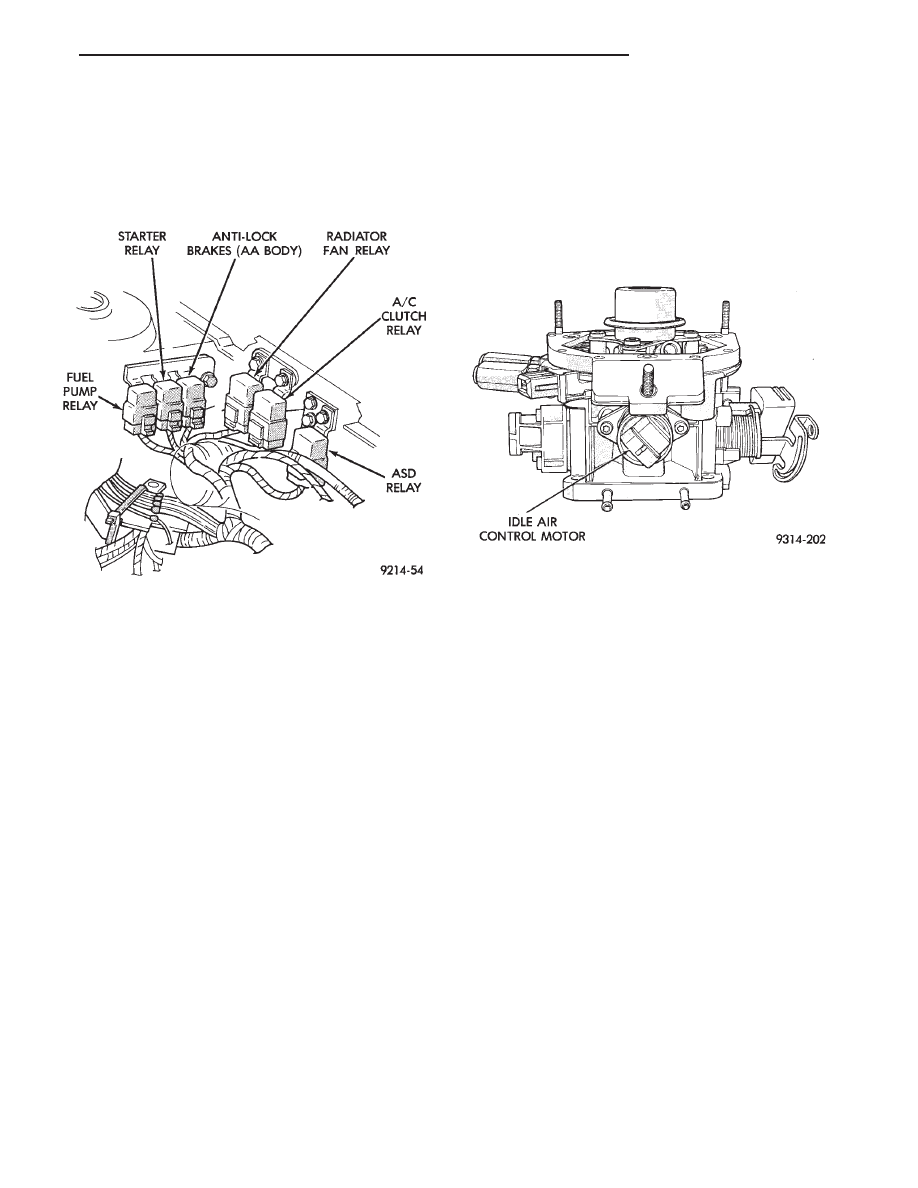
ON AA and AP models, the A/C clutch relay is
mounted to the inner fender panel, next to the driv-
ers side strut tower (Fig. 10).
AUTO SHUTDOWN (ASD) RELAY AND FUEL PUMP
RELAY—PCM OUTPUT
The PCM operates the auto shutdown (ASD) relay
and fuel pump relay through one ground path. The
PCM operates the relays by switching the ground
path on and off. Both relays turn on and off at the
same time.
The ASD relay connects battery voltage to the fuel
injector and ignition coil. The fuel pump relay con-
nects battery voltage to the fuel pump and oxygen
sensor heating element.
The PCM turns the ground path off when the igni-
tion switch is in the Off position. Both relays are off.
When the ignition switch is in the On or Crank po-
sition, the PCM monitors the distributor pick-up sig-
nal.
From
the
distributor
signal,
the
PCM
determines engine speed and ignition timing (coil
dwell). If the PCM does not receive a distributor sig-
nal when the ignition switch is in the Run position,
it will de-energize both relays. When the relays are
de-energized, battery voltage is not supplied to the
fuel injector, ignition coil, fuel pump and oxygen sen-
sor heating element.
On AC, AG and AJ models, the ASD relay and fuel
pump relay are located in the power distribution cen-
ter. Refer to the Wiring and Component Identifica-
tion section of Group 8W.
On AA and AP models, the ASD relay and fuel
pump relay are mounted on the drivers side fender
well, next to the strut tower (Fig. 10).
IDLE AIR CONTROL MOTOR—PCM OUTPUT
The idle air control motor is mounted on the throt-
tle body (Fig. 11). The PCM operates the idle air con-
trol motor. The PCM adjusts engine idle speed
through the idle air control motor to compensate for
engine load or ambient conditions.
The throttle body has an air bypass passage that
provides air for the engine at idle (the throttle blade
is closed). The idle air control motor pintle protrudes
into the air bypass passage and regulates air flow
through it.
The PCM adjusts engine idle speed by moving the
idle air control motor pintle in and out of the bypass
passage. The adjustments are based on inputs the
PCM receives from the throttle position sensor, speed
sensor (distributor pick-up coil), coolant temperature
sensor, and various switch operations (brake, park/
neutral, air conditioning). Deceleration die out is also
prevented by increasing airflow when the throttle is
closed quickly after a driving (speed) condition.
EVAP CANISTER PURGE SOLENOID—PCM
OUTPUT
Vacuum for the Evaporative Canister is controlled
by the EVAP Canister Purge Solenoid (Fig. 12). The
solenoid is controlled by the PCM.
The PCM operates the solenoid by switching the
ground circuit on and off based on engine operating
conditions. When grounded, the solenoid energizes
and prevents vacuum from reaching the evaporative
canister. When not energized, the solenoid allows
vacuum to flow to the canister.
During warm-up and for a specified time period af-
ter hot starts, the PCM grounds the purge solenoid.
Vacuum does not operate the evaporative canister
valve.
Fig. 10 Relay Identification
Fig. 11 Idle Air Control Motor
Ä
FUEL SYSTEMS
14 - 29