Chevrolet Silverado / GMC Sierra. Manual - part 601

Fig. 85: View Of Oil Pressure Sensor
Courtesy of GENERAL MOTORS CORP.
13. Install the oil pressure sensor.
Tighten: Tighten the oil pressure sensor to 41 N.m (30 lb ft).
CAMSHAFT INSTALLATION
Tools Required
J 7872 Dial Indicator Set
Installation
Fig. 86: View Of Camshaft, Camshaft Gear & Camshaft Thrust Plate
Courtesy of GENERAL MOTORS CORP.
1. Install the camshaft thrust plate to the camshaft.
2. Install the camshaft driven gear.
2008 Chevrolet Silverado 1500
2008 ENGINE Engine Mechanical - 6.6L - Cab & Chassis Sierra, Cab & Chassis Silverado, Sierra & Silverado
3. Install a new camshaft driven gear bolt.
Leave the bolt finger tight.
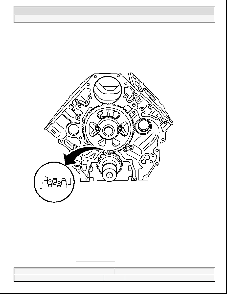
Fig. 87: View Of Camshaft Gear Aligned With Crankshaft Gear
Courtesy of GENERAL MOTORS CORP.
4. Install the camshaft and gear assembly into the cylinder block, aligning the camshaft gear to
the crankshaft gear as shown.
NOTE:
Refer to Fastener Notice .
2008 Chevrolet Silverado 1500
2008 ENGINE Engine Mechanical - 6.6L - Cab & Chassis Sierra, Cab & Chassis Silverado, Sierra & Silverado

5. Install the camshaft thrust plate bolts.
Tighten: Tighten the camshaft thrust plate bolts to 22 N.m (16 lb ft).
Fig. 88: Using Exciter Ring Bolt To Secure Spring Tension
Courtesy of GENERAL MOTORS CORP.
6. Remove the exciter ring bolt that was installed to hold the spring tension of the two piece
IMPORTANT: Use a suitable tool to relieve the spring tension while
removing the locking bolt.
2008 Chevrolet Silverado 1500
2008 ENGINE Engine Mechanical - 6.6L - Cab & Chassis Sierra, Cab & Chassis Silverado, Sierra & Silverado
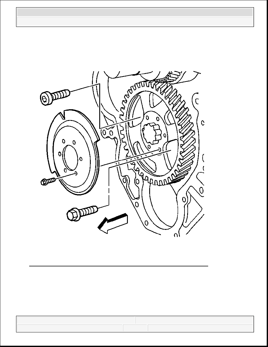
cam gear.
Fig. 89: View Of Camshaft Exciter Ring, Bolts & Thrust Plate Bolts
Courtesy of GENERAL MOTORS CORP.
7. Install the camshaft position sensor exciter ring to the camshaft gear.
8. Install the camshaft position sensor exciter ring bolts.
Tighten: Tighten the camshaft position sensor exciter ring bolts to 9 N.m (80 lb in).
2008 Chevrolet Silverado 1500
2008 ENGINE Engine Mechanical - 6.6L - Cab & Chassis Sierra, Cab & Chassis Silverado, Sierra & Silverado