Chevrolet Silverado / GMC Sierra. Manual - part 442
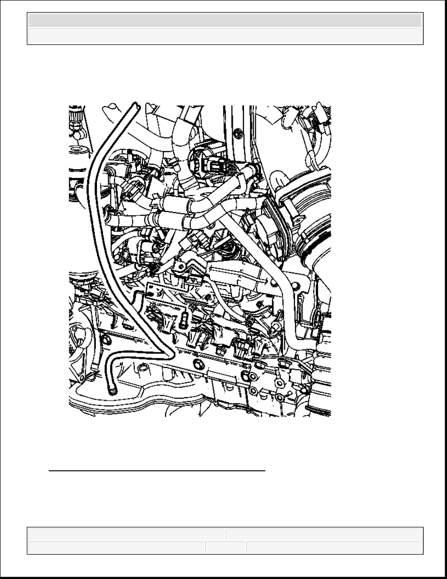
Fig. 94: View Of Oil Level Indicator Tube & Bolt
Courtesy of GENERAL MOTORS CORP.
1. Install NEW O-ring seals onto the oil level indicator tube.
2. Lightly lubricate the O-ring seals with engine oil.
2008 Chevrolet Silverado 1500
2008 ENGINE Engine Mechanical - 6.6L - Cab & Chassis Sierra, Cab & Chassis Silverado, Sierra & Silverado
3. Install the oil level indicator tube.
4. Install the oil level indicator tube bolt at the indicator tube bracket.
Tighten: Tighten the bolt to 21 N.m (15 lb ft).
5. Install the starter motor. Refer to Starter Motor Replacement (6.6L) .
6. Install the exhaust manifold. Refer to Exhaust Manifold Replacement - Right Side
(6.6L) .
7. Install the oil level indicator.
VALVE ROCKER ARM COVER REPLACEMENT - UPPER LEFT SIDE
Removal Procedure
1. Remove the intake manifold cover. Refer to Intake Manifold Cover Replacement.
2. Drain the cooling system. Refer to Cooling System Draining and Filling (Vac-N-Fill) or
Cooling System Draining and Filling (Static Fill) .
3. Disconnect the negative battery cable. Refer to Battery Negative Cable Disconnection
and Connection (w/Single Battery) or Battery Negative Cable Disconnection and
Connection (w/Auxiliary Battery) or Battery Negative Cable Disconnection and
Connection (w/Dual Batteries) .
4. Remove the charged air cooler inlet duct. Refer to Charge Air Cooler Inlet Pipe
Replacement .
NOTE:
Refer to Fastener Notice .
IMPORTANT: After removing the charged air cooler duct, cover the
turbocharger opening with tape in order to prevent entry of
objects.
2008 Chevrolet Silverado 1500
2008 ENGINE Engine Mechanical - 6.6L - Cab & Chassis Sierra, Cab & Chassis Silverado, Sierra & Silverado
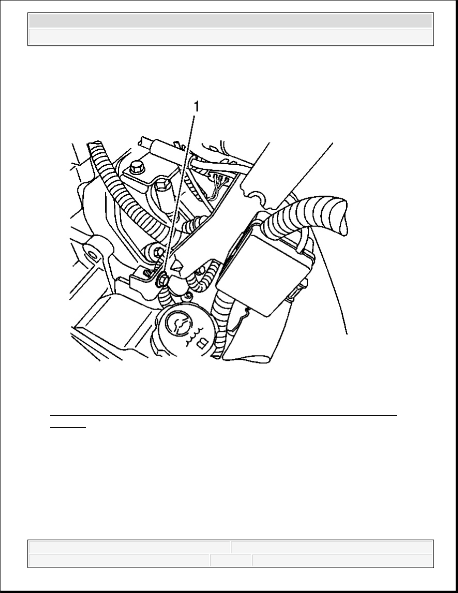
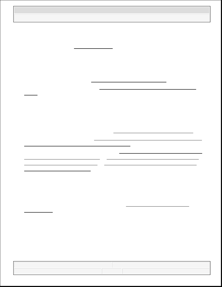
Fig. 95: View Of Battery Cable Junction Block Bolt At Power Steering Pump
Bracket
Courtesy of GENERAL MOTORS CORP.
5. Remove the battery cable to generator nut.
6. If equipped, remove the battery cable to the auxiliary generator.
7. Remove the battery cable harness clip from the bracket.
8. Remove the battery cable junction block bolt (1) from the power steering pump.
9. Move and secure the battery cables out of the way.
2008 Chevrolet Silverado 1500
2008 ENGINE Engine Mechanical - 6.6L - Cab & Chassis Sierra, Cab & Chassis Silverado, Sierra & Silverado
Fig. 96: View Of Fuel Line Bracket & Nut
Courtesy of GENERAL MOTORS CORP.
10. Disconnect the fuel lines. Refer to Metal Collar Quick Connect Fitting Service .
11. Remove the fuel hose bracket nut.
2008 Chevrolet Silverado 1500
2008 ENGINE Engine Mechanical - 6.6L - Cab & Chassis Sierra, Cab & Chassis Silverado, Sierra & Silverado