Chevrolet Silverado / GMC Sierra. Manual - part 227
SCHEMATIC AND ROUTING DIAGRAMS
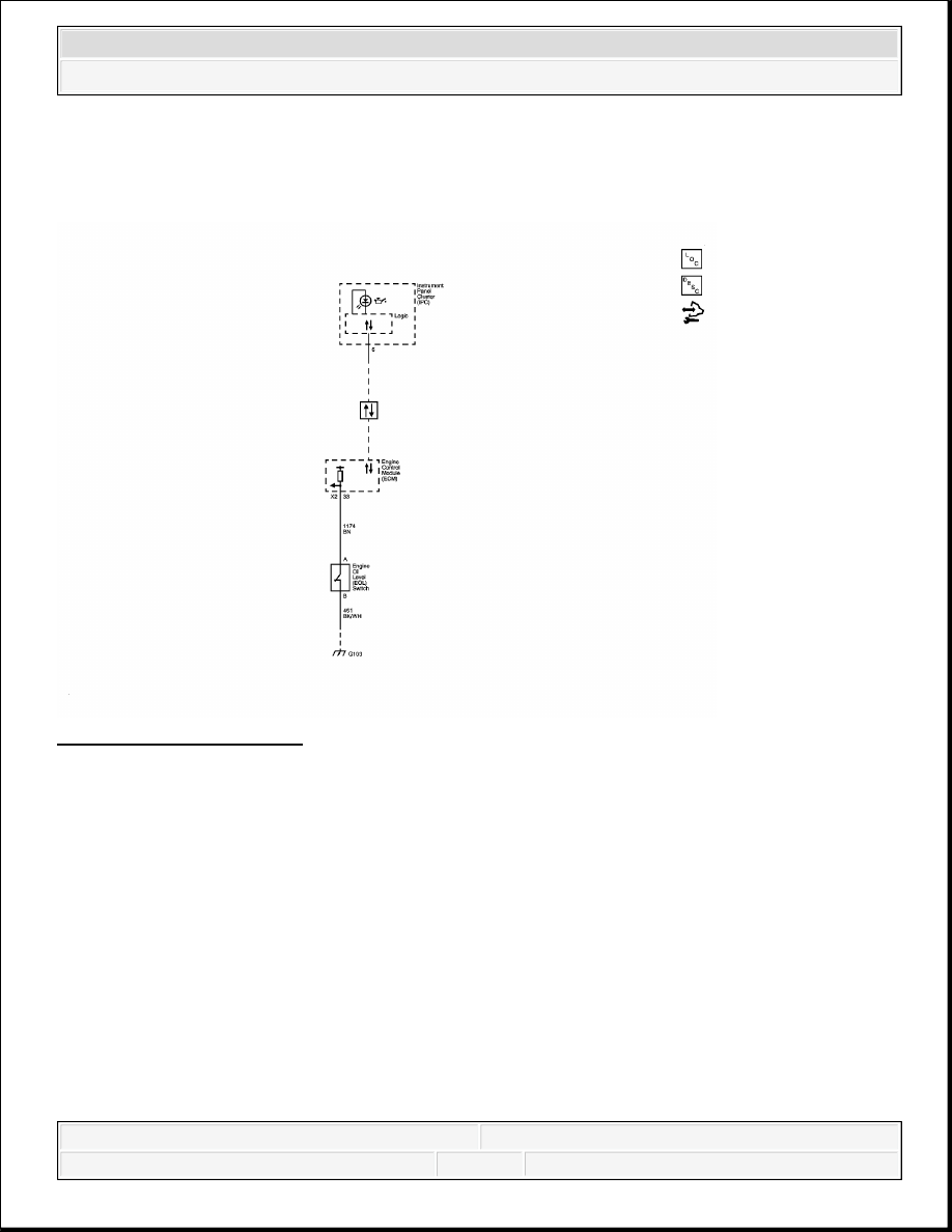
ENGINE MECHANICAL SCHEMATICS
Fig. 6: Engine Mechanical
Courtesy of GENERAL MOTORS CORP.
COMPONENT LOCATOR
DISASSEMBLED VIEWS
2008 Hummer H2
2008 ENGINE Engine Mechanical - 6.2L - H2

Fig. 7: Intake Manifold/Upper Engine
Courtesy of GENERAL MOTORS CORP.
2008 Hummer H2
2008 ENGINE Engine Mechanical - 6.2L - H2

Callout
Component Name
100
Engine Block
307
Engine Coolant Air Bleed Pipe
308
Engine Coolant Air Bleed Pipe O-Ring Seal
308
Engine Coolant Air Bleed Pipe O-Ring Seal
309
Bolt
312
Bolt
313
Engine Coolant Air Bleed Pipe Hole Cover
500
Intake Manifold
506
Bolt
507
Nut
508
Throttle Body
509
Throttle Body Seal
510
Sequential Multi-Port Fuel Injector Assembly with Fuel Rail
511
Bolt
512
Bolt
513
Intake Manifold Seal
514
Intake Manifold Gasket
537
O-Ring Seal
538
Bolt
555
Engine Valley Cover
556
Gasket
557
Fuel Injection Fuel Rail Bracket
706
Engine Oil Pressure Sensor
712
Fuel Injection Fuel Rail Stop
713
Bolt
714
Manifold Absolute Pressure (MAP) Sensor
715
MAP Sensor O-Ring Seal
729
Evaporative (EVAP) Emission Canister Purge Tube
730
EVAP Emission Canister Purge Solenoid Valve
731
EVAP Emission Canister Port Cap
734
EVAP Emission Service Valve
735
EVAP Emission Canister Purge Tube
2008 Hummer H2
2008 ENGINE Engine Mechanical - 6.2L - H2
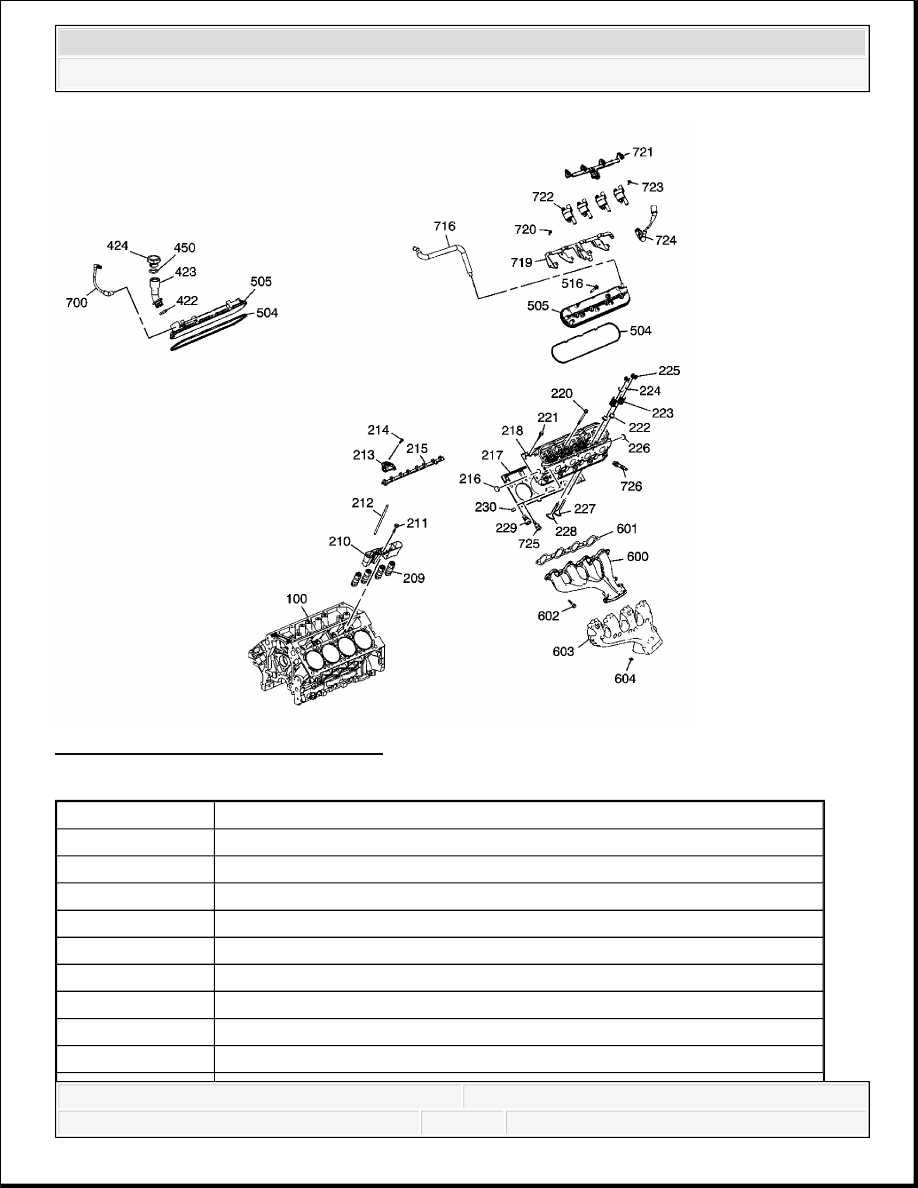
Fig. 8: Cylinder Head/Upper Engine
Courtesy of GENERAL MOTORS CORP.
Callout
Component Name
100
Engine Block
209
Valve Lifter
210
Valve Lifter Guide
211
Valve Lifter Guide Bolt
212
Valve Push Rod
213
Valve Rocker Arm
214
Valve Rocker Arm Pivot Support Bolt
215
Valve Rocker Arm Pivot Support
216
Cylinder Head Core Hole Plug
2008 Hummer H2
2008 ENGINE Engine Mechanical - 6.2L - H2