Content .. 1933 1934 1935 1936 ..
Chevrolet Silverado / GMC Sierra. Manual - part 1935

Fig. 118: View Of Vacuum Brake Booster Hose
Courtesy of GENERAL MOTORS CORP.
31. If replacing the intake manifold, perform the following steps, otherwise proceed to step 21
of the installation procedure.
32. Place the intake manifold on a clean work surface.
33. Reposition the brake booster vacuum hose clamp at the intake manifold.
34. Remove the brake booster vacuum hose from the intake manifold nipple.
2008 Chevrolet Silverado 1500
2008 ENGINE Engine Mechanical - 4.8L, 5.3L, 6.0L, 6.2L, or 7.0L - Cab & Chassis Sierra, Cab & Chassis Silverado,
Sierra & Silverado

Fig. 119: View Of Upper Intake Manifold Cover & Nut
Courtesy of GENERAL MOTORS CORP.
35. Remove the upper intake manifold cover nut.
36. Remove the upper intake manifold cover.
2008 Chevrolet Silverado 1500
2008 ENGINE Engine Mechanical - 4.8L, 5.3L, 6.0L, 6.2L, or 7.0L - Cab & Chassis Sierra, Cab & Chassis Silverado,
Sierra & Silverado

Fig. 120: View Of MAP Sensor & Retainer
Courtesy of GENERAL MOTORS CORP.
37. Remove the manifold absolute pressure (MAP) sensor retainer.
38. Remove the MAP sensor.
2008 Chevrolet Silverado 1500
2008 ENGINE Engine Mechanical - 4.8L, 5.3L, 6.0L, 6.2L, or 7.0L - Cab & Chassis Sierra, Cab & Chassis Silverado,
Sierra & Silverado
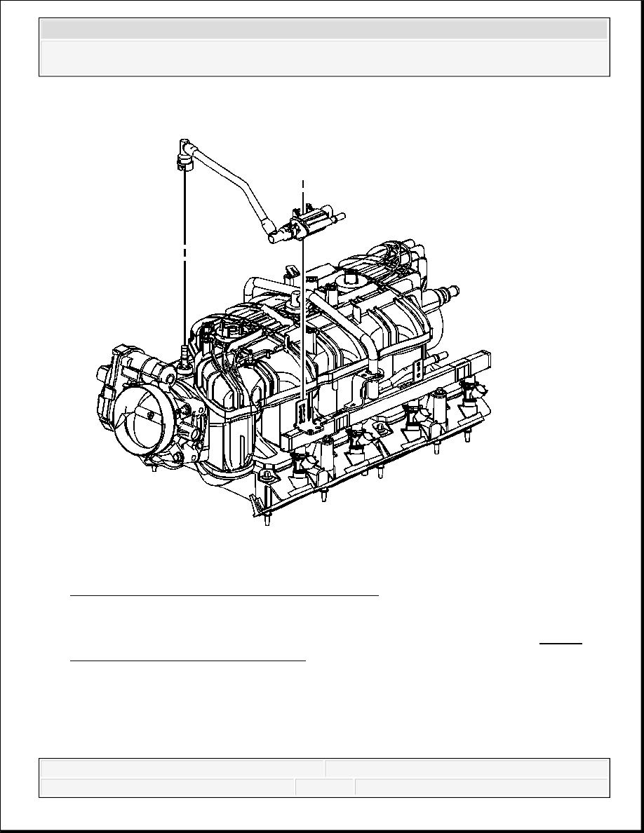
Fig. 121: View Of EVAP Tube & Purge Solenoid
Courtesy of GENERAL MOTORS CORP.
39. Disconnect the EVAP tube quick connect fitting at the intake manifold. Refer to Plastic
Collar Quick Connect Fitting Service .
40. Disengage the retainer securing the EVAP canister purge solenoid to the fuel rail.
41. Remove the EVAP tube and purge solenoid.
2008 Chevrolet Silverado 1500
2008 ENGINE Engine Mechanical - 4.8L, 5.3L, 6.0L, 6.2L, or 7.0L - Cab & Chassis Sierra, Cab & Chassis Silverado,
Sierra & Silverado
Content .. 1933 1934 1935 1936 ..