Content .. 1563 1564 1565 1566 ..
Chevrolet Silverado / GMC Sierra. Manual - part 1565
The front propeller shaft transmits rotating force from the transfer case to the front differential
when the transfer case is engaged. The front propeller shaft connects to the transfer case using a
splined slip joint.
One Piece Propeller Shaft Description
A 1 piece propeller shaft uses a splined slip joint to connect the driveline to the transmission or
transfer case.
Two Piece Propeller Shaft Description
There are 3 universal joints used on the two piece propeller shaft, A center bearing assembly is
used to support the propeller shaft connection point, and help isolate the vehicle from vibration.
Propeller Shaft Phasing Description
The propeller shaft is designed and built with the yoke lugs (ears) in line with each other. This
produces the smoothest running shaft possible. A propeller shaft designed with built in yoke lugs
in line is known as in - phase. An out of phase propeller shaft often causes vibration. The
propeller shaft generates vibration from speeding up and slowing down each time the universal
joint goes around. The vibration is the same as a person snapping a rope and watching the wave
reaction flow to the end. An in phase propeller shaft is similar to 2 persons snapping a rope at the
same time and watching the waves meet and cancel each other out. A total cancellation of
vibration produces a smooth flow of power in the drive line. All splined shaft slip yokes are
keyed in order to ensure proper phasing.
Universal Joint Description
The universal joint is connected to the propeller shaft. The universal consist of 4 caps with needle
bearings and grease seals mounted on the trunnions of a cross or spider. These bearings and caps
are greased at the factory and no periodic maintenance is required. There are 2 universal joints
used in a one piece propeller shaft and 3 used in two piece propeller shaft. The bearings and caps
are pressed into the yokes and held in place with snap rings, except for 2 bearings on some
models witch are strapped onto the pinion flange of the differential. Universal joints are designed
to handle the effects of various loads and rear axle windup conditions during acceleration and
braking. The universal joint operates efficiently and safely within the designed angle variations.
when the design angles are exceeded, the operational life of the joint decreases.
Center Bearing Description
Center bearings support the driveline when using 2 or more propeller shafts. The center bearing is
a ball bearing mounted in a rubber cushion that attaches to a frame crossmember. The
2008 Chevrolet Silverado 1500
2008 DRIVELINE/AXLE Propeller Shaft - Cab & Chassis Sierra, Cab & Chassis Silverado, Sierra & Silverado

manufacturer prelubricates and seals the bearing. The cushion allows vertical motion at the
driveline and helps isolate the vehicle from vibration.
SPECIAL TOOLS AND EQUIPMENT
SPECIAL TOOLS
Illustration
Tool Number/ Description
J 9522-3
U Joint Bearing Separator
J 9522-5
U Joint Bearing Spacer Remover - Use with J
9522-3
J 43218 Clamp Pliers - Narrow Jaw
2008 Chevrolet Silverado 1500
2008 DRIVELINE/AXLE Propeller Shaft - Cab & Chassis Sierra, Cab & Chassis Silverado, Sierra & Silverado

2008 BRAKES
Drum Brakes - Cab & Chassis Sierra, Cab & Chassis Silverado, Sierra & Silverado
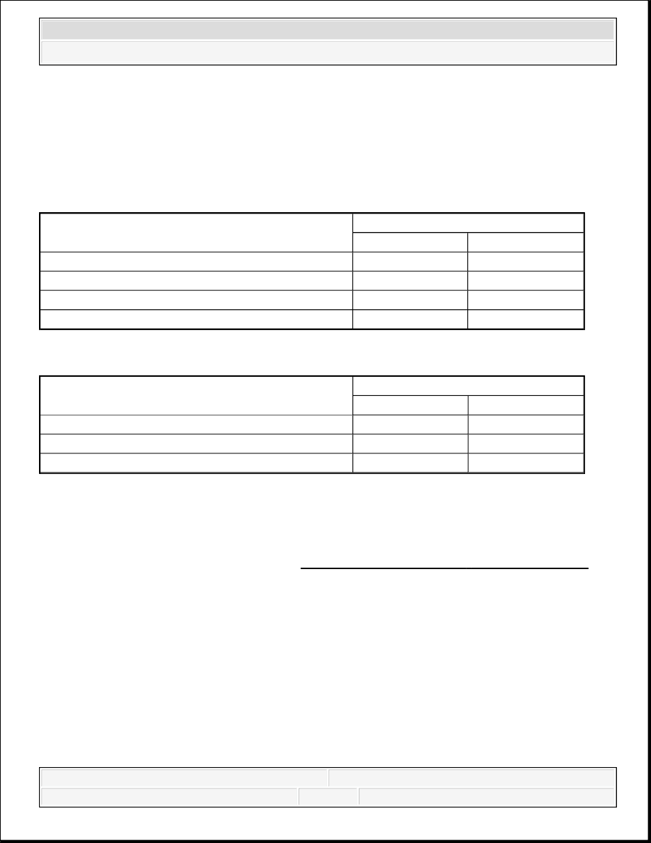
SPECIFICATIONS
FASTENER TIGHTENING SPECIFICATIONS
DRUM BRAKE COMPONENT SPECIFICATIONS
DIAGNOSTIC INFORMATION AND PROCEDURES
DIAGNOSTIC STARTING POINT - DRUM BRAKES
Begin the drum brake system diagnosis with Diagnostic Starting Point - Hydraulic Brakes .
The use of the Diagnostic Starting Point leads to the identification of the correct procedure for
diagnosing the system and where the procedure is located.
BRAKE DRUM DIAMETER MEASUREMENT
Application
Specification
Metric
English
Backing Plate Bolts
135 N.m
100 lb ft
Bleeder Valve
9 N.m
80 lb in
Brake Pipe Fitting
19 N.m
14 lb ft
Wheel Cylinder Bolts
18 N.m
13 lb ft
Brake Drum Specifications
Specification
Metric
English
Maximum Allowable Diameter
296.5 mm
11.673 in
Maximum Allowable Radial Runout
0.06 mm
0.0024 in
Maximum Allowable Scoring
1.5 mm
0.06 in
2008 Chevrolet Silverado 1500
2008 BRAKES Drum Brakes - Cab & Chassis Sierra, Cab & Chassis Silverado, Sierra & Silverado
2008 Chevrolet Silverado 1500
2008 BRAKES Drum Brakes - Cab & Chassis Sierra, Cab & Chassis Silverado, Sierra & Silverado

Fig. 1: Measuring Brake Drum
Courtesy of GENERAL MOTORS CORP.
1. Clean the brake shoe lining contact surface of the brake drum with denatured alcohol or an
equivalent brake cleaner.
2. Using a brake drum micrometer calibrated in thousands of an inch, measure and record the
largest diameter of the brake drum at 4 or more points, equally spaced around the drum.
Ensure that the measurements are only taken within the brake shoe lining contact area and
that the micrometer is positioned the same distance from the outside edge of the drum for
each measurement.
3. The maximum allowable diameter :
Specification: Maximum allowable measurement 296.5 mm (11.673 in)
4. If the largest diameter measurement of the brake drum is less than the maximum allowable
diameter, the drum may be able to be resurfaced, depending upon surface and wear
conditions which may be present.
5. If the largest diameter measurement of the brake drum is equal to or greater than the
2008 Chevrolet Silverado 1500
2008 BRAKES Drum Brakes - Cab & Chassis Sierra, Cab & Chassis Silverado, Sierra & Silverado
Content .. 1563 1564 1565 1566 ..