Content .. 999 1000 1001 1002 ..
Chevrolet Silverado / GMC Sierra. Manual - part 1001

Fig. 521: Pressure Switch Manifold
Courtesy of GENERAL MOTORS CORP.
The PSM is a multiple-switch assembly made up of 3 N/O pressure switches, PS1 (4), PS2 (3),
and PS3 (2) and 1 N/C pressure switch. N/O pressure switches, PS1, PS2, and PS3, correspond
to shift valves SS1, SS2, and SS3. Fluid pressures are fed from shift valves SS1, SS2, and SS3 to
the manual selector valve and to the pressure switches based on the positions of the valves and
shift selector. The shift valve fluid pressures reflect the logic condition at the corresponding
solenoids. This logic indicates the current transmission operating range to the TCM.
The 3 fluid pressure switches corresponding to the shift valves are N/O, contacts not touching,
when no fluid pressure is present, so that electrical current is stopped at the switch. When fluid
pressure is routed to the switch, it moves the diaphragm and upper contact so that the contact
element touches both the positive and ground contacts. This closes the circuit and allows current
to flow from the positive contact and through the switch.
Pressure switch 4 (PS4) (1) corresponding to REVERSE is N/C, since fluid pressure is always
present unless the selector valve is moved to REVERSE. The PSM also contains a transmission
fluid temperature (TFT) sensor thermistor (5) for sump temperature. Changes in sump fluid
temperature are indicated by changes in sensor resistance. Increasing temperature causes
2008 Chevrolet Silverado 1500
2008 TRANSMISSION Automatic Transmission - Allison - Cab & Chassis Sierra, Cab & Chassis Silverado, Sierra &
Silverado
decreased sensor resistance. The resistance value is then relayed to the TCM as an input for shift
control.
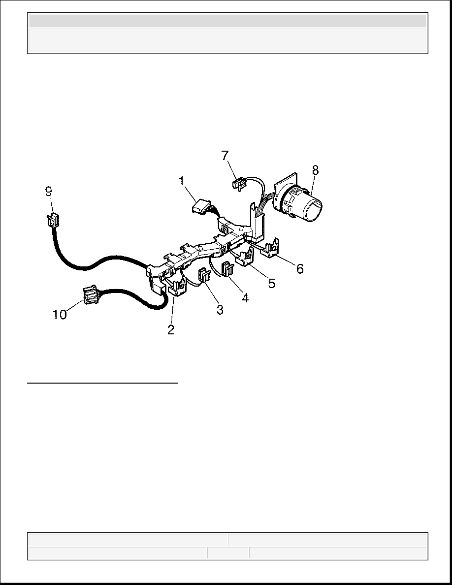
Internal Wiring Harness
Fig. 522: Internal Wiring Harness
Courtesy of GENERAL MOTORS CORP.
The internal wiring harness has connectors for shift solenoids SS1 (7), SS2 (3) and SS3 (4),
PCS1 (6) and PCS2 (5), TCC pressure control solenoid (TCC PCS) (2), and the PSM (1). There
is also a connector for the modulated main (MOD MAIN) pressure solenoid (9) and the IMS
(10). All of these connectors go to the main electrical connector (8). The transmission main
electrical connector transports signals from these connectors to the TCM via the external harness.
NEUTRAL - ENGINE RUNNING
In Neutral (N), pressure control solenoid 1 (PCS1) is in the normally closed state (de-energized),
PCS2 is in the normally open state (de-energized), shift solenoid 1 (SS1), SS2, and SS3 are
energized, and the torque converter clutch pressure control solenoid (TCC PCS) remains de-
2008 Chevrolet Silverado 1500
2008 TRANSMISSION Automatic Transmission - Allison - Cab & Chassis Sierra, Cab & Chassis Silverado, Sierra &
Silverado
energized.
SS1, SS2, and SS3 supply control main pressure to the top of shift valve 1, shift valve 2, and shift
valve 3, stroking the valves against spring force.
With shift valve 1 stroked, control main pressure is directed through shift valve 1 to pressure
switch 1, turning the switch on. With shift valve 2 stroked, the exhaust path is blocked for the
control main pressure being supplied through an orifice to pressure switch 2, and the pressure
raises to control main and pressure switch 2 turns on. With shift valve 3 stroked, the exhaust path
is blocked for the control main pressure being supplied through an orifice to pressure switch 3,
and the pressure raises to control main and pressure switch 3 turns ON. With pressure switch 1,
pressure switch 2, and pressure switch 3 ON, feedback is provided to the transmission control
module (TCM) that shift valve 1, shift valve 2, and shift valve 3 are stroked.
Normally closed PCS1 blocks the exhaust of the PCS1 signal pressure, raising the signal pressure.
PCS1 signal pressure strokes pressure control valve 1, raising the PCS1 pressure which is
directed to shift valve 2. In the stroked position, shift valve 2 routes fluid to the low and reverse
clutch, applying the clutch. All other clutches are exhausted.
With only one clutch applied, the transmission is in Neutral (N).
If electrical power is interrupted while Neutral (N) is selected, SS1, SS2, and SS3 are de-
energized and shift valve 1 de-strokes. Due to valve timing, when power is lost, shift valve 1
strokes faster than shift valve 3. When shift valve 1 de-strokes, control main pressure is fed
through shift valve 1 to the top of shift valve 3, keeping the valve stroked. Normally closed PCS1
continues to block the exhaust of the solenoid signal pressure (solenoid signal remains control
main). The solenoid signal pressure on top of pressure control valve 1 produces maximum
pressure, which is routed to shift valve 2. Shift valve 2 stays stroked due to the "latching" effect
of the low and reverse clutch pressure acting on two different diameter lands. In the stroked
position, pressure continues to be routed to the low and reverse clutch, keeping the clutch
applied. Since only one clutch is applied, the transmission remains in Neutral (N).
If electrical power is interrupted with the transmission in Neutral (N) and the manual selector
valve is moved to a forward range or reverse, the transmission stays in neutral because shift valve
3 stays de-stroked and main pressure is blocked from reaching the manual selector valve.
If the engine is shutdown and restarted with the electrical power interrupted to the TCM, shift
valve 1, shift valve 2, and shift valve 3 remain de-stroked. Normally closed PCS1 blocks the
exhaust of the PCS1 signal pressure (signal pressure becomes control main). The solenoid signal
pressure on top of PCV1 produces maximum pressure, which is routed to shift valve 2. In the de-
stroked position, shift valve 2 routes fluid to the 3rd, 5th, and reverse clutch. All other clutches
2008 Chevrolet Silverado 1500
2008 TRANSMISSION Automatic Transmission - Allison - Cab & Chassis Sierra, Cab & Chassis Silverado, Sierra &
Silverado

are exhausted, so the transmission remains in Neutral (N). When shift valve 3 is de-stroked, main
pressure is routed through shift valve 3 to the manual selector valve. If a forward range is
selected, the manual selector valve routes fluid to the 1-2-3-4 clutch. 3rd, 5th, and reverse clutch
remains on with the 1-2-3-4 clutch, resulting in third range being attained for limp home
capability. If Reverse (R) is selected, the selector valve directs fluid through the TCC valve and
shift valve 2 to low and reverse clutch. 3rd, 5th, and reverse clutch remains on with low and
reverse clutch, resulting in Reverse (R) range being attained.
Fig. 523: Identifying Hydraulic Circuits Used In Neutral
Courtesy of GENERAL MOTORS CORP.
FIRST RANGE
When the selector lever is moved from Neutral (N) to Drive (D), the transmission shifts from
neutral to first range operation. Shift solenoid 1 (SS1), SS2, and SS3 remain energized. Pressure
control solenoid 1 (PCS1) and the torque converter clutch (TCC) solenoid remain de-energized.
Shift valve 1, shift valve 2, and shift valve 3 stay in the stroked position. With normally closed
PCS1 de-energized, pressure control valve 1 continues to supply full control pressure through
shift valve 2 to the low and reverse clutch, keeping the clutch applied. During the shift, PCS2
energizes, blocking the exhaust of the PCS2 signal pressure, causing the pressure to rise. The
PCS2 signal pressure strokes pressure control valve 2, opening the pressure control valve 2
2008 Chevrolet Silverado 1500
2008 TRANSMISSION Automatic Transmission - Allison - Cab & Chassis Sierra, Cab & Chassis Silverado, Sierra &
Silverado
Content .. 999 1000 1001 1002 ..