Chery Tiggo 5 (T21). Manual - part 503


  Index      Chery     Chery Tiggo 5 (T21) - service repair manual 2014 year


Search            


Content   ..  501  502  503  504   ..


Chery Tiggo 5 (T21). Manual - part 503


 47–

28

47

Front Door Assembly

Removal

HINT:

 Use the same procedures for the right side and left side.

 Procedures listed below are for the left side.

1. Turn off all the electrical equipment and ignition switch.
2. Disconnect the negative battery cable.
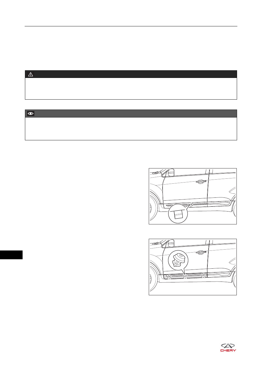
3. Remove the front left door trim board garnish. 

a. Using a screwdriver wrapped with protective tape, pry 

up the claws on front door trim board garnish.

b. Remove the front left door trim board garnish.

4. Remove the front left door trim board assembly.

a. Using a screwdriver wrapped with protective tape, pry 

up the clips on front door trim board assembly.

b. Remove the front door trim board assembly.

WARNING

 When removing front door assembly, an assistant is needed to hold front door to prevent front door from 

dropping to cause accidents during operation.

CAUTION

 Be sure to wear safety equipment to prevent accidents when removing front door assembly.
 Try to prevent body paint surface from being scratched when removing front door assembly.

RT21470321

RT21470322

 47–

29

47

5. Disconnect the front left door connector.

a. Using a screwdriver wrapped with protective tape, pry 

up the front door dust boot.

b. Using a screwdriver wrapped with protective tape, pry 

up the claws on connector.

c. Disconnect the front left door connector (arrow).

6. Remove the front left door frame weatherstrip.

a. Remove the clip from the front door frame 

weatherstrip, and remove the front left door frame 
weatherstrip.

7. Remove the front left door buffer block.

a. Using a screwdriver wrapped with protective tape, 

remove the front door buffer blocks (arrow).

8. Remove the front left door protector assembly (

See page 47-23

).

9. Remove the front left door assist grip mounting bracket assembly.

RT21470330

RT21470360

RT21470340

 47–

30

47

a. Remove 2 fixing screws (arrow) from the front door 

assist grip mounting bracket assembly.

(Tightening torque: 1.5 ± 0.5 N·m)

b. Remove the front left door assist grip mounting 

bracket assembly.

10.Remove the front left door protective film assembly.

a. Disengage the wire harness clips (arrow).

RT21470350

CAUTION

 Avoid damage to front door protective film when removing front door protective film assembly.
 Place front door protective film assembly properly after removal, and avoid adhesive sticker on front door 

protective film assembly from sticking to other components.

RT21470380

 47–

31

47

b. Remove the front left door protective film assembly by 

gently pulling it along edges from one corner of the 
front left door protective film assembly.

11.Remove the front left woofer assembly. (

See page 39-15

).

12.Remove the left outside rear view mirror assembly (

See page 44-7

).

13.Remove the front left door key cylinder protective cover (

See page 37-44

).

14.Remove the front left door outside handle.

a. Disconnect the connector (arrow) from the front door 

outside handle.

b. Slide and pull the front door outside handle in the 

direction of arrow as shown in the illustration, and 
remove it.

RT21470370

RT21470390

RT21470381


Content   ..  501  502  503  504   ..