Chery Tiggo 5 (T21). Manual - part 478
 

  Index      Chery     Chery Tiggo 5 (T21) - service repair manual 2014 year


Search            


Content   ..  476  477  478  479   ..


Chery Tiggo 5 (T21). Manual - part 478


44–

4

44

Specifications

Torque Specifications

Tool

General Tool

Description

Torque (N·m)

Outside Rear View Mirror Assembly Fixing Bolt

6 ± 1

Inside Rear View Mirror Assembly Fixing Screw

1.5 ± 0.5

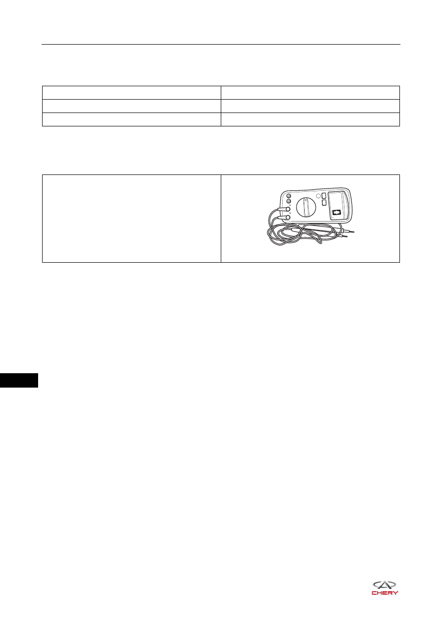
Digital Multimeter

RCH0000002

44–

5

44

Circuit Diagram

Power Rear View Mirror Control System

ET21440010

8

9

3

15

5

2

1

3

7

LH
MIRROR

UP

UP

DOWN 

DOWN 

RH

RH

LH

LH

LH
MIRROR

RH
MIRROR

RH
MIRROR

4

B

BrR

BrR

BrR

BrR

BrY

BrY

BrY

BrB

BrB

BrB

BrG

BrG

BrG

BrL

BrL

BrL

RY

6

M

M

M

IGNITION SWITCH

ON OR START

REAR VIEW
MIRROR
ADJUSTMENT
SWITCH

POWER REAR 
VIEW MIRROR 
MOTOR

POWER REAR 
VIEW MIRROR 
MOTOR

1

4

13

BB

1

2

1

3

RF15

7.5A

M

7

9

8

7

8

5

3

GR

15

4

13

BB

1

3

WL

WL

GR

C16

C6

BCM

7

1

2

3

4

5

6

7

8

9 10 11 12

13

85

85

87

87 30

87 30

30

86

86

85

86

14 15 16 17 18 19 20 21 22 23 24

25

27

26

1

2

3

4

5

6

7

8

9

10

1

2

3

4

5

6

7

8

9

10

11

12

13

14

15

16

17

18

19

20

21

22

18 17 16 15 14 13 12 11 10

9

8

7

6

5

4

3

2

1

C1

C10 C11 C12 C13 C14 C15 C16 C17 C18

C2 C3 C4 C5

C6 C7 C8 C9

C20

C19

1

2

3

8

9

10

11

12

13

14

15

16

4

5

6

7

INSTRUMENT 
PANEL FUSE 
AND RELAY 
BOX A

I-007

I-008

I-006

B-003

B-041
F-007

B-061
H-002

B-041

B-043

F-007

B-061

H-002

B-040

F-007

I-035

B-059

I-037

B-062

B-036

B

I-007

B

I-008

W

I-006

W

I-035

1

4

7 10 13 16

2

5

8 11 14 17

3

6

9 12 15 18

1

4

7

10

13

16

2

5

8

11

14

17

3

6

9

12

15

18

Gr

B-041

W

B-040

1

4

7 10 13 16

2

5

8 11 14 17

3

6

9 12 15 18

W

B-061

4

1

14

13

9

W

F-005

F-005

W

H-008

H-008

W

B-043

44–

6

44

DIAGNOSIS & TESTING

Problem Symptoms Table

HINT:
Use the table below to help determine the cause of the problem symptoms. Check each suspected area in 
sequence.  Repair or replace the faulty components, or adjust them as necessary.

Repair & Inspection Items

Visual inspection can reduce unnecessary test and diagnostic time, so pay attention to inspection of the 
following items:
1. Check if fuse is damaged.
2. Check if wire harnesses and connectors related to rear view mirror are worn, pierced, pinched or partially 

broken.

3. Check wire harnesses and connectors related to rear view mirror for break, bend, protrusion or corroded 

terminals.

4. Check if terminal contact pins of connectors related to rear view mirror are in good condition.

Symptom

Suspected Area

See page

Outside rear view mirror cannot operate

Fuse

51-36

Outside rear view mirror adjustment switch 
assembly

44-12

Outside rear view mirror assembly

44-7

Wire harness or connector

-

Outside rear view mirror intermittent 
malfunction

Ground

51-29

Wire harness or connector

-

44–

7

44

ON-VEHICLE SERVICE

Outside Rear View Mirror Assembly

Removal

HINT:

 Use the same procedures for the right side and left side.

 Procedures listed below are for the left side.

1. Turn off all the electrical equipment and ignition switch.
2. Disconnect the negative battery cable.
3. Remove the front left door protector assembly (

See page 47-23

).

4. Remove the left outside rear view mirror assembly.

a. Disconnect the outside rear view mirror connector (1).
b. Remove 3 fixing bolts (arrow) from outside rear view 

mirror assembly.

(Tightening torque: 6 ± 1 N·m)

c. Remove the left outside rear view mirror assembly.

CAUTION

 Make sure to wear safety equipment to prevent accidents when removing rear view mirror assembly.
 Operate carefully to prevent damage to the components when removing outside rear view mirror 

assembly.

 Prevent the interior and body paint from being scratched when removing outside rear view mirror 

assembly.

1

RT21440020


Content   ..  476  477  478  479   ..