Chery Tiggo 5 (T21). Manual - part 364
32–
47
32
ET21320080
32
31
30
29
28
16
15
14
13
12
11
10
9
8
7
6
5
4
3
2
1
27
26
25
24
23
22
21
20
19
18
17
Gr
I-046
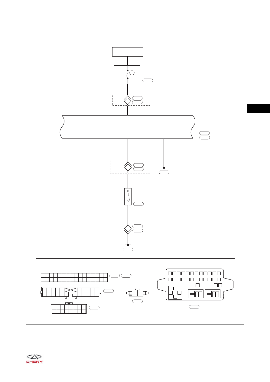
SRS
CONTROL
MODULE
I-046
IGNITION SWITCH
ON OR START
10A
RF08
INSTRUMENT
PANEL FUSE
AND RELAY BOX
I-007
B
I-045
16
1
2
3
4
5
6
7
8
9 10 11 12
13
85
85
87
87 30
87 30
30
86
86
85
86
14 15 16 17 18 19 20 21 22 23 24
25
27
26
B
I-007
1
2
3
4
5
6
7
8
9
10
11
12
13
14
15
16
17
18
19
20
21
22
W
I-006
BR
BR
B
B
B
1
2
20
15
I-045
11
FRONT
PASSENGER
SEAT BELT
SWITCH
1
2
I-006
B
B-050
B-050
B-003
I-006
B-003
8
R
R
1
4
I-036
B-055
*2
B-072
16 15 14 13 12 11 10
8
7
6
5
4
3
2
1
9
W
I-036
*2: SRS control module connector is B-072
*1: SRS control module connector is I-046
B
B-072
*1