Chery Tiggo 5 (T21). Manual - part 355
 

  Index      Chery     Chery Tiggo 5 (T21) - service repair manual 2014 year


Search            


Content   ..  353  354  355  356   ..


Chery Tiggo 5 (T21). Manual - part 355


32–

11

32

 Wiggle related wire harnesses and connectors and observe if signal is interrupt in the related circuit.
 If possible, try to duplicate the conditions under which the DTC was set.
 Look for the data that has changed or the DTC to be reset during the wiggle test.
 Look for broken, bent, protruded or corroded terminals.
 Inspect the airbag components and mounting areas for damage, foreign matter, etc. that will cause 

incorrect signals.

 Check and clean all wire harness connectors and grounding parts related to the current DTC.
 Remove the SRS control module assembly from the malfunctioning vehicle and install it to a new vehicle 

and perform a test. If DTC cannot be cleared, the SRS control module assembly is malfunctioning. If DTC 
can be cleared, reinstall the SRS control module assembly to original vehicle.

 If multiple trouble codes were set, refer to the circuit diagrams to look for any common ground circuit or 

power supply circuit applied to the DTC.

 Refer to Technical Bulletin that is applied to the malfunction.

Ground Inspection

Groundings are very important to the entire circuit system, which are normal or not can seriously affect the 
entire circuit system. Groundings are often exposed to moisture, dirt and corrosive elements. Corrosion (rust) 
can increase resistance which will change the way in which a circuit works.
Electronically controlled circuits are very sensitive to proper grounding. A loose or corroded ground can affect 
the electronically controlled circuit. Perform the following operations when checking the ground points:
1. Remove the ground nut.
2. Check all contact surfaces for tarnish, dirt, rust, etc.
3. Clean as necessary to ensure that contacting is in a good condition.
4. Reinstall the ground nut securely.
5. Check if add-on accessories interfere with the ground circuit.
6. If several wire harnesses are crimped into one ground eyelet terminal, check if the wire harnesses are 

installed correctly. Make sure all wire harnesses are clean, securely fastened and providing a good ground 
path.

Diagnosis Procedure

HINT:
Use following procedures to troubleshoot the Supplemental Restraint System (SRS). 

Standard voltage: 11 to 14 V
If voltage is below 11 V, recharge or replace the battery before proceeding to next step.

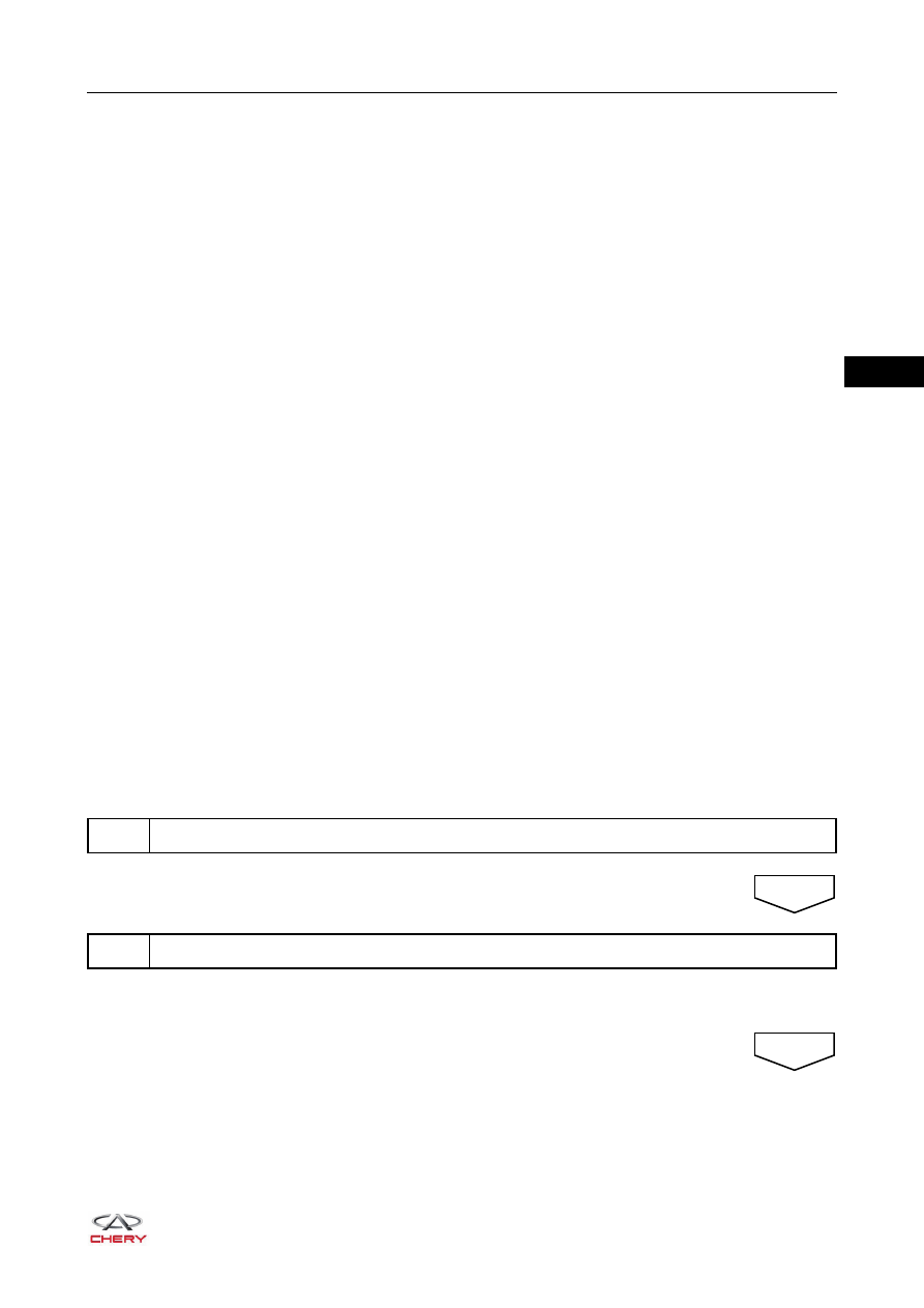
1

Vehicle brought to workshop

2

Check battery voltage

NEXT

NEXT

32–

12

32

HINT:
An activation prevention mechanism is built in the airbag system connector. When the connector is 
disconnected, this mechanism cuts off the circuit by bringing the short spring plate into contact with the 
terminals, thus insulating the circuit from external power sources to prevent accidental airbag activation.

To release the activation prevention mechanism, insert a piece of paper with the same thickness as the male 
terminal between terminals and short spring plate to disconnect the connection.

During circuit troubleshooting for the airbag system, make sure to cut off the battery power source, and wait 
for at least 90 seconds to discharge the system condenser.
When performing electrical diagnosis and test, always refer to the relevant circuit diagram for the special 
circuit and component information.

3

Check SRS warning light

4

Check for DTCs (current DTC and history DTC)

NEXT

For current DTC, go to step 5

For history DTC, go to step 6

DTC 
occurs

No 

DTC

5

Diagnostic Trouble Code (DTC) chart

6

Circuit inspection

WARNING

 DO NOT release the activation prevention mechanism unless specially directed by the troubleshooting 

procedure.

7

Repair

NEXT

NEXT

NEXT

32–

13

32

8

Clear DTCs (current DTC and history DTC)

9

Check for DTCs (current DTC and history DTC)

NEXT

Go to step 5

Go to next step

DTC 
output

No DTC

output 

10

Confirmation test

11

End

NEXT

NEXT

32–

14

32

Diagnostic Trouble Code (DTC) Chart

DTC Code

DTC Definition

B0001-11 

Front Airbag Driver Loop Circuit Short to Ground

B0001-12 

Front Airbag Driver Loop Circuit Short to Battery

B0001-1A

Front Airbag Driver Loop Circuit Resistance Below Threshold

B0001-1B

Front Airbag Driver Loop Circuit Resistance Above Threshold

B0001-1C

Front Airbag Driver Loop Circuit Voltage Out of Range 

B0010-11

Front Airbag Passenger Loop Circuit Short to Ground 

B0010-12

Front Airbag Passenger Loop Circuit Short to Battery 

B0010-1A

Front Airbag Passenger Loop Circuit Resistance Below Threshold 

B0010-1B

Front Airbag Passenger Loop Circuit Resistance Above Threshold 

B0010-1C

Front Airbag Passenger Loop Circuit Voltage Out of Range 

B0070-11

Belt Pretensioner Front Driver Loop Circuit Short to Ground

B0070-12

Belt Pretensioner Front Driver Loop Circuit Short to Battery 

B0070-1A

Belt Pretensioner Front Driver Loop Circuit Resistance Below Threshold 

B0070-1B

Belt Pretensioner Front Driver Loop Circuit Resistance Above Threshold 

B0070-1C

Belt Pretensioner Front Driver Loop Circuit Voltage Out of Range 

B0072-11

Belt Pretensioner Front Passenger Loop Circuit Short to Ground

B0072-12

Belt Pretensioner Front Passenger Loop Circuit Short to Battery 

B0072-1A

Belt Pretensioner Front Passenger Loop Circuit Resistance Below Threshold 

B0072-1B

Belt Pretensioner Front Passenger Loop Circuit Resistance Above Threshold

B0072-1C

Belt Pretensioner Front Passenger Loop Circuit Voltage Out of Range

B1231-12

Buckle Switch Front Passenger (BLFP) Circuit Short to Battery 

B1231-1C

Buckle Switch Front Passenger (BLFP) Circuit Voltage Out of Range

B1232-12

PDM (Passenger Detection Mat) Switch Circuit Short to Battery

B1232-1C

PDM (Passenger Detection Mat) Switch Circuit Voltage Out of Range

B1210-00 

Front Deployment

B1211-00 

BT Deployment

B125A-00

Crash Counter Reached Max

B1240-96

ICM Airbag Lamp Failed

B1251-49

Electronic Control Unit (ECU), Internal Electronic Failure

B1250-16

Battery Voltage Circuit Voltage Below Threshold 

B1250-17

Battery Voltage Circuit Voltage Above Threshold

U1300-55

Software Configuration Error


Content   ..  353  354  355  356   ..