Chery Tiggo 5 (T21). Manual - part 318


  Index      Chery     Chery Tiggo 5 (T21) - service repair manual 2014 year


Search            


Content   ..  316  317  318  319   ..


Chery Tiggo 5 (T21). Manual - part 318


30–

4

30

Operation

The circular motion of the steering wheel is converted into linear motion of the rack by engaging the rack and 
pinion inside the steering gear. The rack can push and pull the tie rod by lateral motion, thus changing the 
direction of the front wheel.
The EPS controller controls the rotating direction of steering motor and the assisting current level based on 
the torque sensor signals to finish the steering assist. When the vehicle is not turning, the EPS controller does 
not send command to the steering motor controller, and the steering motor does not operate.

Specifications

Torque Specifications
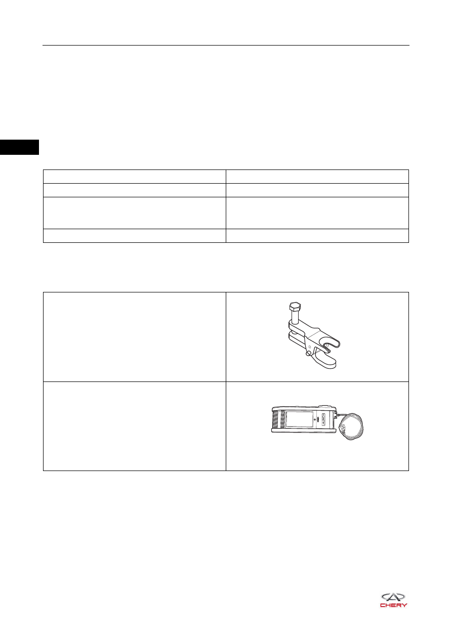
Tools

Special Tools

Description

Torque (N·m)

Ball Pin Locking Nut

35 ± 3

Coupling Bolt between Steering Gear Input Shaft 
and Steering Column with Intermediate Shaft 
Assembly

60 ± 5

Steering Gear Fixing Bolt

120 ± 10

Ball Pin Separator

X-431 3G Diagnostic Tester 

RCH0000024

RCH0000001

ཽ⪔⊳䖜

30–

5

30

General Tool

Digital Multimeter

RCH0000002

30–

6

30

Circuit Diagram

ET21300010

BATTERY

R

R

B

MF09

80A

7.5A

RF07

7

A1

B1

IGNITION SWITCH
    ON OR START

INSTRUMENT
PANEL 
FUSE AND 
RELAY BOX

EPS

B2

B3

A2

TO CAN
SYSTEM

YB

GB

CAN L1

CAN H1

B1

B2

B3

B4

B5

B6

B7

B8

B9

B10

1

2

3

4

5

6

7

8

9 10 11 12

13

85

85

87

87 30

87 30

30

86

86

85

86

14 15 16 17 18 19 20 21 22 23 24

25

27

26

B

I-007

B

I-057

I-007

L

E-077

A1

A2

E-077

E-081

E-064

EPS 
POWER

E-064

I-057

30–

7

30

EPS Controller Pin Definition

Vehicle supply: controller supply connector (connector A)

Vehicle signal: controller signal connector (connector B)

RT21300030

1 2 3 4 5

B

A

6 7 8 9 10

Pin

Definition

A

supply positive

B

supply negative

Pin

Definition

1

IGN signal

2

CAN High

3

CAN Low

4

-

5

-

6

Signal ground

7

-

8

-

9

-

10

-


Content   ..  316  317  318  319   ..