Chery Tiggo 5 (T21). Manual - part 295


  Index      Chery     Chery Tiggo 5 (T21) - service repair manual 2014 year


Search            


Content   ..  293  294  295  296   ..


Chery Tiggo 5 (T21). Manual - part 295


26–

35

26

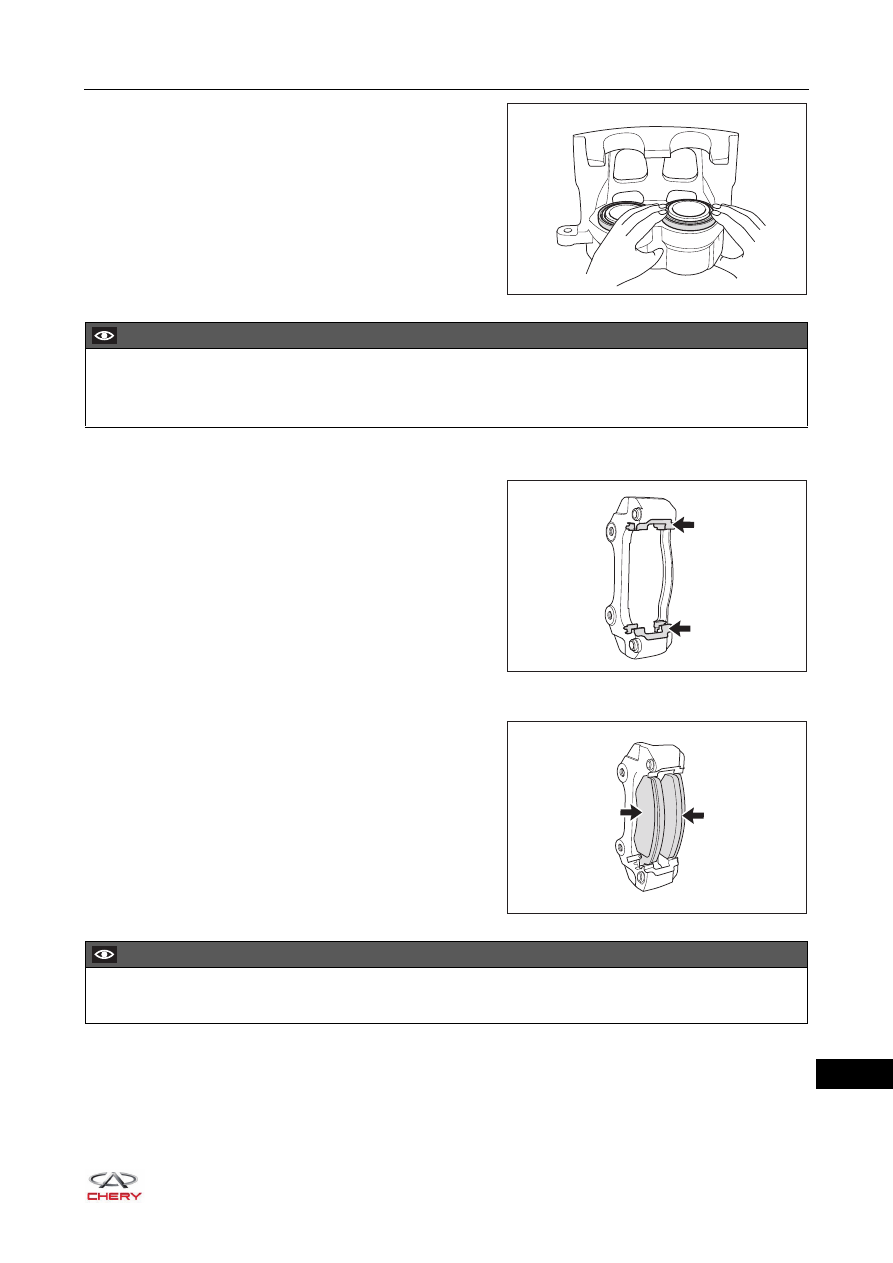
b. Install the brake cylinder dust boot to the brake 

cylinder.

4. Install the brake lining support gasket.

a. Securely install the upper and lower support gaskets 

(arrow) onto the brake caliper fixing bracket.

5. Install the front brake lining.

a. Securely install the inner brake lining and outer brake 

lining (arrow) onto the brake caliper fixing bracket. 
Make sure they are clamped in place.

RT21260480

CAUTION

 Securely install brake cylinder dust boots into front ring grooves (both sides) of disc brake cylinder.
 DO NOT damage brake cylinder dust boot.

RT21260400

RT21260390

CAUTION

 Make sure the contact surface of lining and brake disc is free of oil and grease.

26–

36

26

6. Install the front brake caliper locating bolt guide pin (w/ dust boot).

a. Apply a small amount of grease to the contact surface 

between locating bolt guide pins and guide pin rubber 
dust boots, and securely install the dust boots (arrow) 
to the brake caliper fixing bracket.

7. Install the brake cylinder assembly.

a. Using brake cylinder piston pressing tool, slightly 

retract the brake cylinder piston (both sides).

b. Align the brake caliper locating bolts (arrow) with the 

guide pin hole and securely install the brake cylinder 
assembly.

(Tightening torque: 25 ± 3 N·m)

8. Install the bleeder plug (w/ bleeder plug cap).

a. Securely install the bleeder plug (w/ bleeder plug cap) 

(arrow) to the front brake caliper assembly.

(Tightening torque: 9 - 11 N·m)

RT21260380

RT21260490

RT21260370

RT21260360

26–

37

26

Installation

Installation is in the reverse order of removal.

CAUTION

 Make sure to tighten fixing bolts and nuts to the specified torque during installation. 
 Before installing brake linings, completely retract brake caliper piston back into the bore of brake caliper.
 Depress brake pedal several times to secure the brake linings to brake disc in order to ensure safety 

after installing the brake linings and before moving vehicle.

 Replace brake linings in pairs. DO NOT replace it alone. 
 DO NOT install inner brake lining and outer brake lining reversely. 
 Be sure to check brake system for leakage after installation. Repair or replace malfunctioning parts as 

necessary. 

 Be sure to perform bleeding procedures for brake system after installation. 
 Be sure to add brake fluid to the proper level after installation.

26–

38

26

Front Brake Hose Assembly

Removal

HINT:

 Use the same procedures for the right side and left side.

 Procedures listed below are for the left side.
1. Remove the front left wheel (

See page 24-9

).

2. Drain the brake fluid (

See page 26-13

).

3. Remove the front left brake hose assembly.

a. Disengage the fixing clamp (arrow) and loosen the 

coupling plug (1) between front left brake hose 
assembly and front left brake pipe.

(Tightening torque: 16 ± 2 N·m)

CAUTION

 Be sure to wear necessary safety equipment to prevent accidents when repairing.
 Try to prevent body paint surface from being scratched during removal and installation. 

CAUTION

 Wash off brake fluid immediately if it comes in contact with any paint surface.

ENVIRONMENTAL PROTECTION

 Drained brake fluid should be well kept in a container. Never discard it at will.

1

RT21260500

CAUTION

 DO NOT bend or damage brake tube. 
 DO NOT allow any foreign matter such as dirt and dust to enter brake tube from joint parts.
 After removing brake line, perform sealing treatment to prevent foreign matter from entering.


Content   ..  293  294  295  296   ..