Chery Tiggo 5 (T21). Manual - part 257


  Index      Chery     Chery Tiggo 5 (T21) - service repair manual 2014 year


Search            


Content   ..  255  256  257  258   ..


Chery Tiggo 5 (T21). Manual - part 257


23–

23

23

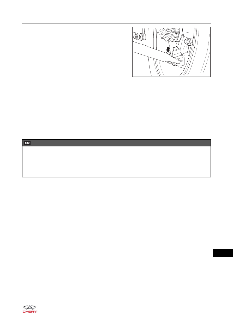
c. Remove the coupling bolt (arrow) between front left 

control arm ball pin assembly and front left control arm 
assembly.

(Tightening torque: 150 ± 10 N·m)

d. Remove the front left control arm ball pin assembly.

Inspection

1. Check control arm ball pin assembly.

a. Check control arm assembly ball pin boot for wear, cracks, deformation, damage or grease leakage. 

Replace as necessary.

b. Check if control arm assembly ball pin rotates smoothly. Replace as necessary.

Installation

Installation is in the reverse order of removal.

RT21230230

CAUTION

 Always tighten coupling bolts and nuts to the specified torque.
 Make sure that ball pin rotates smoothly and is not stuck after installation.
 Check wheel alignment after installation is completed. Adjust the wheel alignment to standard range as 

necessary.

23–

24

23

Front Stabilizer Bar Assembly

Removal

1. Remove the front wheel (

See page 24-9

).

2. Remove the precatalytic converter assembly (

See page 11-10

).

3. Remove the front control arm assembly (

See page 23-20

).

4. Remove the front stabilizer bar assembly.

a. Support the engine and transmission assembly securely with a engine equalizer.
b. Hold the lower end of front link assembly with an inner 

hexagon wrench, remove the coupling nut (arrow) 
between front stabilizer bar and front link assembly 
with a fixing wrench and disengage the front link 
assembly.

(Tightening torque: 45 ± 5 N·m)

c. Remove 2 coupling bolts and nut (arrow) between 

side rail welding assembly and rear mounting cushion 
assembly.

(Tightening torque: 70 ± 5 N·m)

d. Remove 2 coupling bolts (arrow) between front sub 

frame welding assembly and steering gear assembly.

(Tightening torque: 120 ± 10 N·m)

CAUTION

 Be sure to wear necessary safety equipment to prevent accidents.
 Make sure that safety lock of lifter has been locked when removing and installing chassis parts.
 It is not permitted to weld or modify suspension bearing parts.
 When removing and installing chassis parts, replace self-locking nuts and rusted nuts for safety.
 When lowering front sub frame welding assembly, it needs to support engine and transmission assembly 

securely with a engine equalizer to avoid damage.

RT21230240

RT21220220

RT21220240

23–

25

23

e. Remove 2 coupling bolts (arrow) between upper part 

of front sub frame welding assembly and body.

(Tightening torque: 180 ± 10 N·m)

f. Remove 2 coupling bolts (arrow) between rear part of 

front sub frame welding assembly and body.

(Tightening torque: 180 ± 10 N·m)

g. Support the front sub frame welding assembly with 

front stabilizer bar assembly with a transmission 
carrier, and lower it carefully.

h. Remove the coupling bolts (arrow) between front 

stabilizer bar assembly and front sub frame welding 
assembly, and separate them.

(Tightening torque: 25 ± 3 N·m)

RT21220250

RT21220260

RT21220270

RT21230235

23–

26

23

i. Detach the left and right fixing clamps (arrow) from 

front stabilizer bar assembly.

j. Detach the left and right rubber supports (arrow) from 

front stabilizer bar assembly.

Inspection

1. Check front stabilizer bar assembly.

a. Check front stabilizer bar assembly fixing clamps for wear, cracks, deformation or damage. Replace as 

necessary.

b. Check front stabilizer bar assembly rubber supports for dirt, wear, cracks, deformation or damage. 

Replace as necessary.

Installation

Installation is in the reverse order of removal.

RT21230250

RT21230260

CAUTION

 Always tighten coupling bolts and nuts to the specified torque.


Content   ..  255  256  257  258   ..