Chery Tiggo 5 (T21). Manual - part 213
18–
41
18
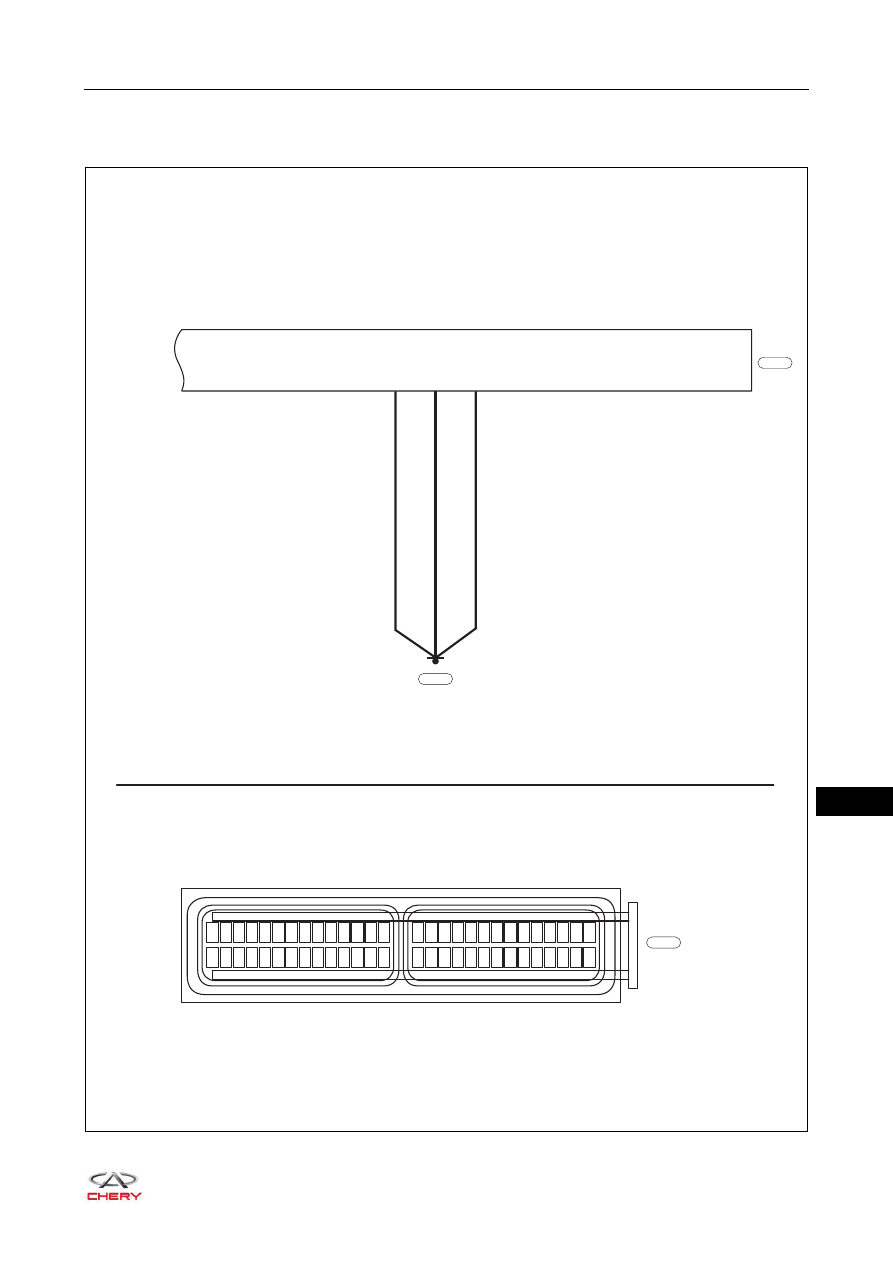
Ground Circuit Test
Ground Circuit
ET21180070
29 30 31 32 33 34 35 36 37 38 39 40 41 42
1 2 3 4 5 6 7 8 9 10 11 12 13 14
43 44 45 46 47 48 49 50 51 52 53 54 55 56
15 16 17 18 19 20 21 22 23 24 25 26 27 28
TCU
B
B
B
24
25
26
E-030
B
E-030
E-087