Chery Tiggo 5 (T21). Manual - part 186


  Index      Chery     Chery Tiggo 5 (T21) - service repair manual 2014 year


Search            


Content   ..  184  185  186  187   ..


Chery Tiggo 5 (T21). Manual - part 186


16–

7

16

ON-VEHICLE SERVICE

Battery

Inspection

1. Check that battery terminals are not loose or corroded.

If battery terminals are corroded, clean them.

2. Check the battery for damage, deformation or leakage. If serious damage, deformation or leakage is 

found, replace the battery.

3. Check the battery voltage.

Turn ignition switch to ON, and turn it off 20 to 30 seconds after turning on the headlights. This will 
eliminate the surface charge on the battery. Measure battery voltage with digital multimeter.

Removal

1. Turn off all the electrical equipment and ignition switch.
2. Remove the battery.

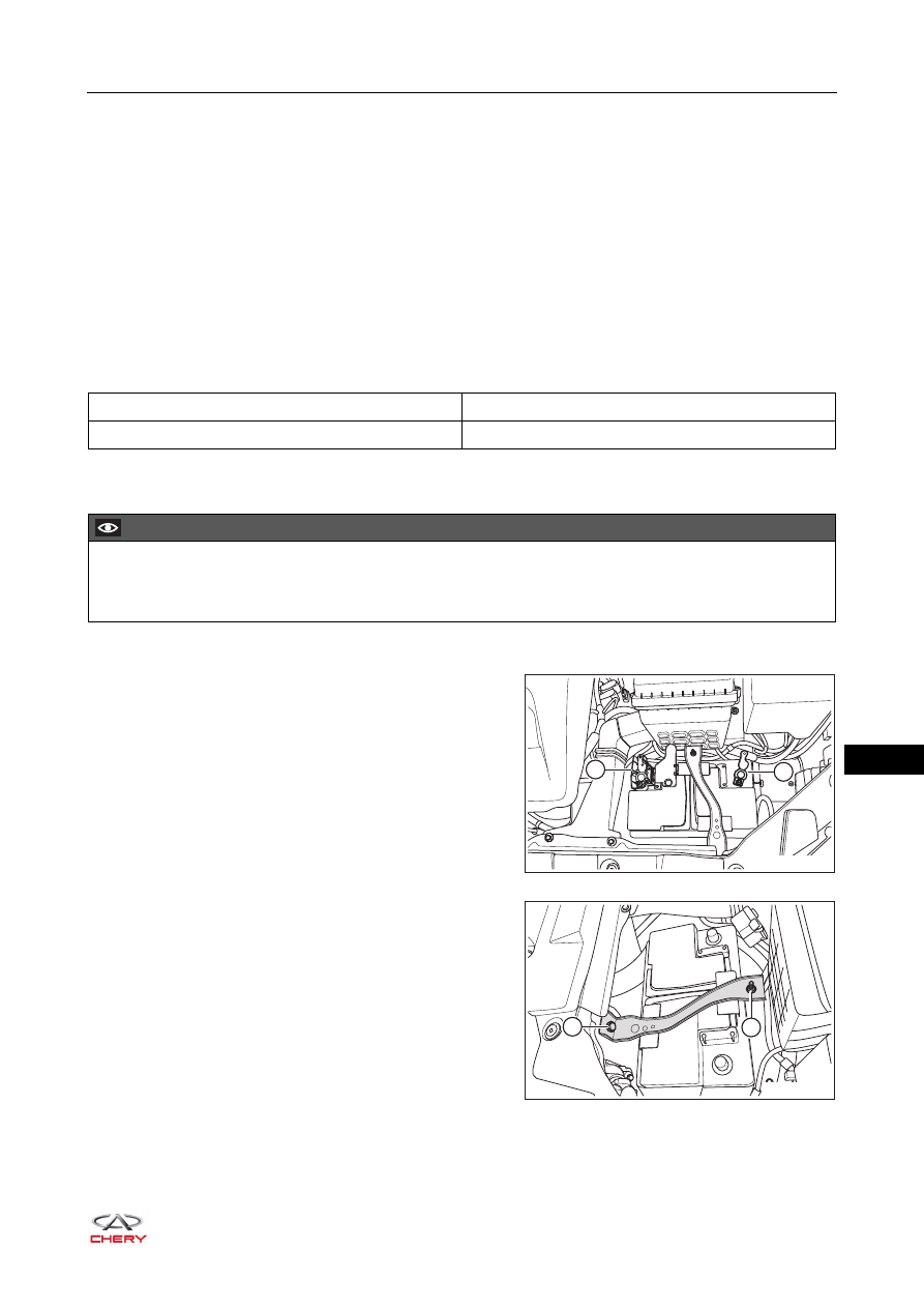
a. Loosen the negative battery cable locking nut, and 

remove the negative (-) battery cable (1).

b. Open the battery positive terminal cover, loosen the 

positive battery cable locking nut, and remove the 
positive (+) battery cable (2).

c.  Remove the battery pressure plate fixing nut (1).

 (Tightening torque: 7 ± 1 N·m)

d. Remove the coupling bolt (2) between battery 

pressure plate and tank upper crossmember.

(Tightening torque: 7 ± 1 N·m)

Testing Temperature

Specification

20°C

12 - 13 V

CAUTION

 Be sure to wear necessary safety equipment to prevent accidents when repairing.
 Try to prevent body paint surface from being scratched during removal and installation.

2

1

RT21160020

2

1

RT21160030

16–

8

16

e. Remove the battery.

Installation

Installation is in the reverse order of removal.

CAUTION

 Please be careful to prevent metal tools from contacting both electrodes of battery at the same time or 

accidentally touching the positive electrode and vehicle body.

CAUTION

 Replace battery with a new one which conforms to the specifications.
 Used battery contains sulfuric acid and lead, so never discard it at will. Please dispose of it at a qualified 

local waste treatment station.

16–

9

16

Battery Tray and Tray Bracket

Removal

1. Turn off all the electrical equipment and ignition switch.
2. Remove the battery (

See page 16-7

).

3. Remove the battery tray.

a. Remove 2 coupling bolts (1) between battery tray and 

air filter bracket.

(Tightening torque: 7 ± 1 N·m)

b. Remove 6 fixing bolts (2) from the battery tray.

(Tightening torque: 20 ± 2 N·m)

c. Remove the battery tray.

4. Remove the battery tray bracket.

a. Remove 4 fixing bolts (arrow) from the battery tray 

bracket.

(Tightening torque: 20 ± 2 N·m)

b. Remove 2 battery tray brackets.

Installation

Installation is in the reverse order of removal.

CAUTION

 Be sure to wear necessary safety equipment to prevent accidents when repairing.
 Try to prevent body paint surface from being scratched during removal and installation.

1

2

RT21160040

RT21160050

16–

10

16

Alternator

Removal

1. Turn off all the electrical equipment and ignition switch.
2. Disconnect the negative battery cable.
3. Remove the engine trim cover assembly (

See page 10-10

).

4. Remove the engine lower right protector assembly (

See page 48-29

).

5. Loosen the accessory drive belt.

a. Put 15# open wrench (or socket) between engine and 

right side-member, and tighten the tensioner pulley 
bolt.

b. Rotate open wrench counterclockwise firmly indicated 

by the arrow shown in the illustration. Loosen the 
accessory drive belt (1) after it is slack.

6. Remove the alternator.

a. Move away the terminal cap, remove the fixing nut (1) 

from alternator output cable, and move away the 
alternator output cable.

(Tightening torque: 18 - 22 N·m)

b. Disconnect the alternator connector (2).

c. Remove 2 fixing bolts (arrow) from the alternator.

(Tightening torque: 20 + 5 N·m)

d. Remove the alternator from alternator bracket.

CAUTION

 Be sure to wear necessary safety equipment to prevent accidents when repairing.
 Try to prevent body paint surface from being scratched during removal and installation.

1

RT21160060

1

2

RT21160070

RT21160080


Content   ..  184  185  186  187   ..