Chery Tiggo 5 (T21). Manual - part 173
15–
27
15
Check for Open
Check for Short
B-056 (J307) or
B-061 (18) -
Battery positive
Always
No continuity
B-056 (J306) or
B-061 (10) -
Battery positive
Always
No continuity
Repair or replace body wire harness and
connector
Multimeter
Connection
Condition
Specified
Condition
NG
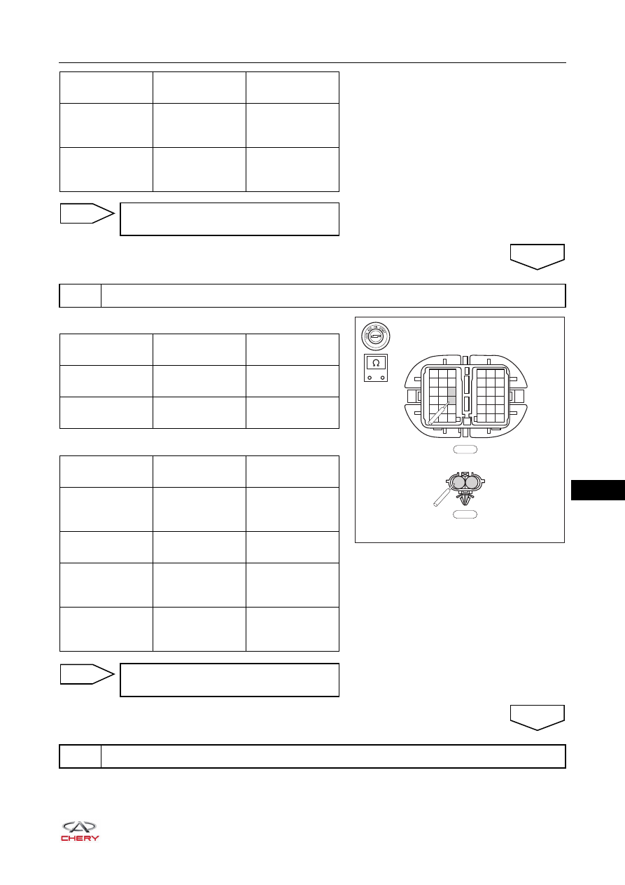
3
Check front left door wire harness and connector
OK
-
+
RT21150220
1
1
2
2
3
3
4 5 6
7 8 9
10 11 12
13 14 15
16
4
7
10
13
16
17
5
8
11
14
17
18
6
9
12
15
18
F-007
1
2
F-003
Multimeter
Connection
Condition
Specified
Condition
F-007 (12) - F-003
(2)
Always
Continuity
F-007 (9) - F-003
(1)
Always
Continuity
Multimeter
Connection
Condition
Specified
Condition
F-007 (12) or
F-003 (2) - Body
ground
Always
No continuity
F-007 (9) or F-003
(1) - Body ground
Always
No continuity
F-007 (12) or
F-003 (2) -
Battery positive
Always
No continuity
F-007 (9) or F-003
(1) - Battery
positive
Always
No continuity
Repair or replace front left door wire
harness and connector
NG
4
Check front right door wire harness and connector
OK