Chery Tiggo 5 (T21). Manual - part 164


  Index      Chery     Chery Tiggo 5 (T21) - service repair manual 2014 year


Search            


Content   ..  162  163  164  165   ..


Chery Tiggo 5 (T21). Manual - part 164


14–

3

14

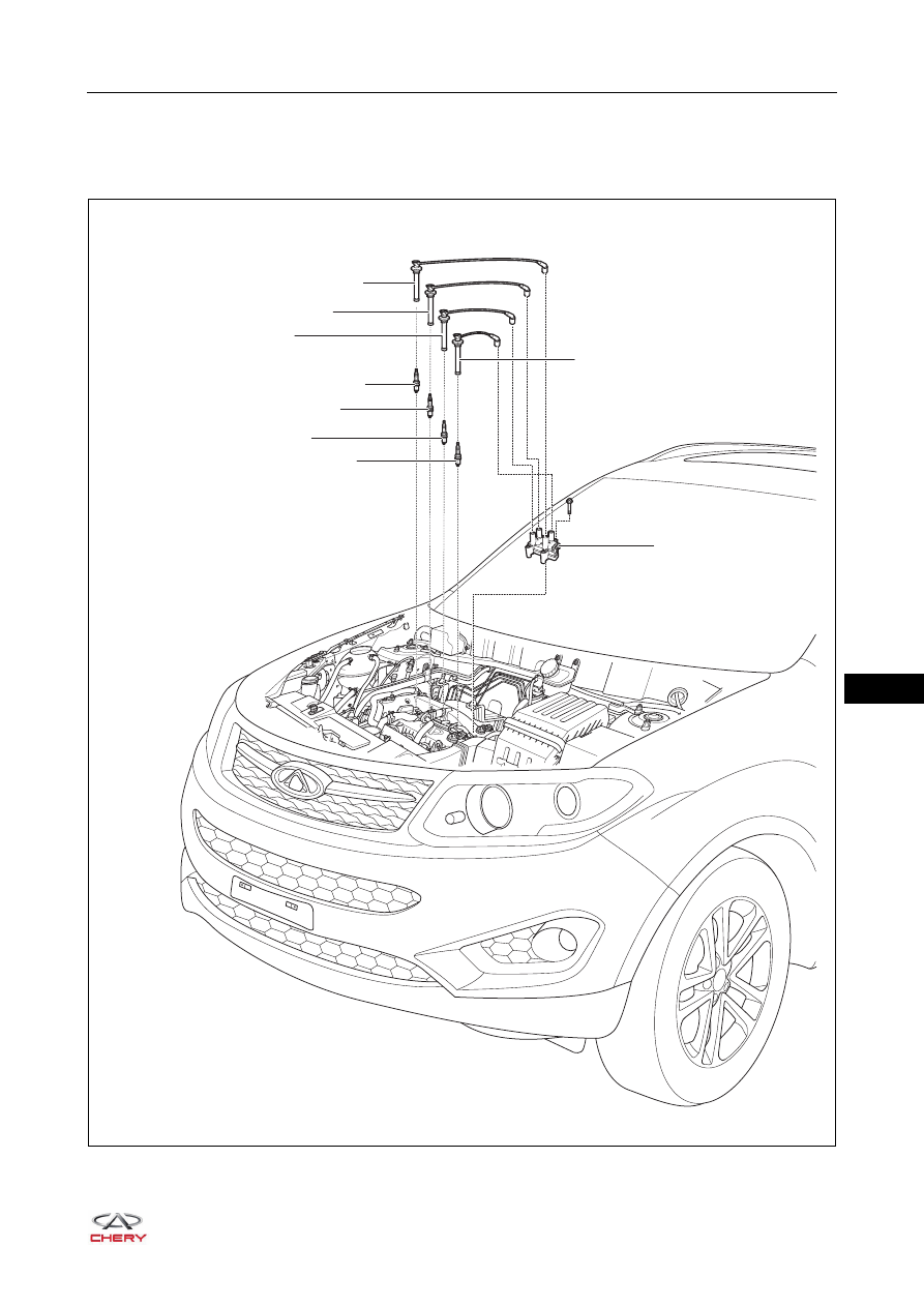
SQR484F IGNITION SYSTEM

GENERAL INFORMATION

Description

RT21140010

×4

MAX

MAX

MIN

MIN

1

2

3

8

4

5

6

7

9

14–

4

14

Operation

This model uses the distributorless ignition system which mainly consists of ignition coils, spark plugs, etc. 
Ignition advance angle is controlled by Engine Control Module (ECM) directly.
Ignition coil consists of two primary windings, two secondary windings, iron core, housing, etc. When the 
primary winding is connected to ground, it is charged. Once ECM cuts off the primary winding circuit, charging 
stops, and at the same time, a high voltage is induced in the secondary winding to enable the spark plug to 
discharge. This ignition system's difference from the ignition coil with distributor is that a spark plug is 
connected to the ignition coil secondary winding at each end, which makes two spark plugs ignite 
simultaneously. Two primary windings turn on/off alternately. Two secondary windings alternately discharge 
accordingly.

Specifications

Torque Specifications

Spark Plug Specifications

Tool

General Tool

1 - Cylinder 1 High-voltage Cable Assembly

2 - Cylinder 2 High-voltage Cable Assembly

3 - Cylinder 3 High-voltage Cable Assembly

4 - Cylinder 1 Spark Plug

5 - Cylinder 2 Spark Plug

6 - Cylinder 3 Spark Plug

7 - Cylinder 4 Spark Plug

8 - Cylinder 4 High-voltage Cable Assembly

9 - Ignition Coil

Description

Torque (N·m)

Spark Plug

30 ± 3

Ignition Coil Fixing Bolt

8 + 3

Engine Type

SQR484F

Spark Plug Type

FR7DTC

Spark Plug Gap (mm)

0.8 - 0.9

Digital Multimeter

RCH0000002

14–

5

14

Circuit Diagram

Ignition System

ET21140010

MT

A1

A2

A3

A4

A5

A6

A7

A8 A9 A10

F12

F24

F11

F23

F10

F22

F9

F21

F8

F20

F7

F19

F6

F18

F5

F17

F4

F16

F3

F15

F2

F14

F1

F13

Gr

E-076

W

E-069

B

E-033

49 50 51

63

64

15

16

31

32

47

48

33 34 35

17 18 19

1

2

3

52 53 54 55 56 57 58 59 60 61 62

36 37 38 39 40 41 42 43 44 45 46

20 21 22 23 24 25 26 27 28 29 30

4

5

6

7

8

9 10 11 12 13 14

ECM
E-033
E-035

ENGINE 
COMPARTMENT 
FUSE AND 
RELAY BOX

E-076

E-069

BATTERY

ECM
MAIN 
RELAY

10A

EF19

10A

EF40

A2

F14

2-20

RL

2-5

Br

A6

2-15

2-16

RR

R

86

30

85

87

E-023

1

2

3

4

5

6

7

8

9

10

11

12

13

14

15

16

17

18

19

20

21

22

23

24

25

26

31

35

39

40

41

42

32

33

36

37

38 34

27

28

29

30

B

E-007

R

GGr

GBr

GGr

GBr

15A

C4

EF07

IGNITION
COIL

CYL1

CYL4

CYL3

CYL2

3

1-36

1-35

1

2

33

32

E-007
E-038

E-018

C1

C2

C3 C4

C5

C6

C7

C8 C9 C10

L

E-023

1 2 3 4

B

E-018

37 38 39 40 41 42 43 44 45 46

47

48

25 26 27 28 29 30 31 32 33 34

35

36

13 14 15 16 17 18 19 20 21 22

23

24

1

2

3

4

5

6

7

8

9 10

11

12

B

E-035

14–

6

14

DIAGNOSIS & TESTING

Problem Symptoms Table

Symptom

Suspected Area

See page

Stall

Ignition coil

14-10

Spark plug

14-12

Camshaft position sensor

06-248

Intake VVT control valve

06-242

Exhaust VVT control valve

06-242

Wire harness

-

Knock

Ignition coil

14-10

Knock sensor

06-245

ECM

06-256

Difficult to start

Battery

16-7

Ignition coil

14-10

Spark plug

14-12

Engine hesitation, power drop, unstable 
performance

Spark plug

14-12

Engine speed sensor

06-249

Intake VVT control valve

06-242

Exhaust VVT control valve

06-242

Camshaft position sensor

06-248

ECM

06-256

Rough, unstable idling or stall

Spark plug

14-12

Ignition coil

14-10

ECM

06-256


Content   ..  162  163  164  165   ..