Chery Tiggo 5 (T21). Manual - part 130


  Index      Chery     Chery Tiggo 5 (T21) - service repair manual 2014 year


Search            


Content   ..  128  129  130  131   ..


Chery Tiggo 5 (T21). Manual - part 130


08–

9

08

DIAGNOSIS & TESTING

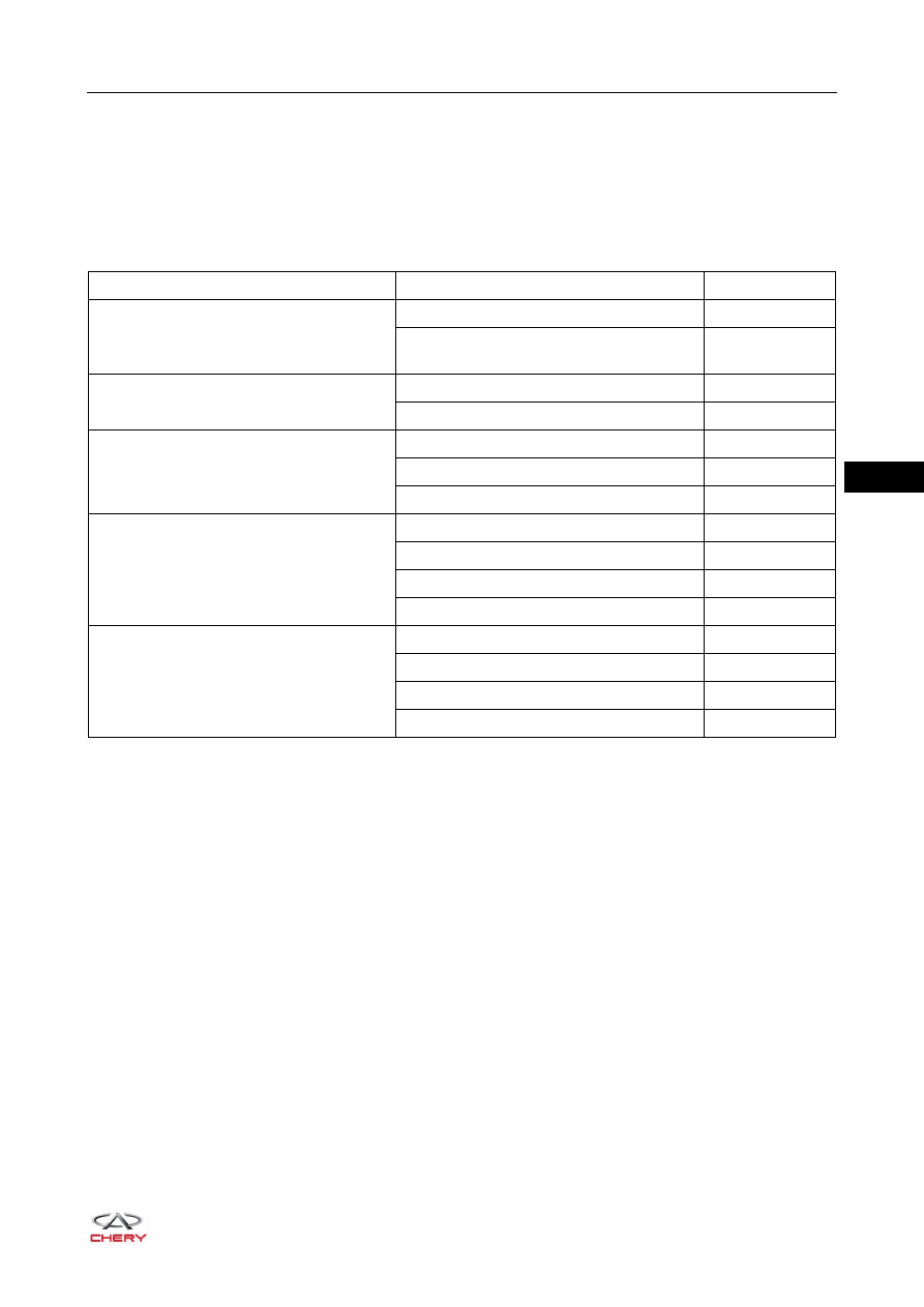
Problem Symptoms Table

HINT:
Use the table below to help determine the cause of problem symptoms. Check each suspected area in 
sequence. Repair or replace the faulty components, or adjust as necessary.

Symptom

Suspected Area

See page

Fuel pressure in fuel supply system is too 
low

Fuel filter assembly (blocked)

08-12

Electric fuel pump assembly (strainer 
blocked)

08-14

Fuel pressure in fuel supply system is too 
high

Fuel injector (clogged)

08-26

Electric fuel pump assembly

08-14

Electric fuel pump assembly has loud 
operating noise and operates delay

Low fuel level

-

Electric fuel pump assembly relay

-

Electric fuel pump assembly

08-14

Injector is clogged and leaks

Fuel filter assembly (blocked)

08-12

Fuel injector

08-26

Poor fuel quality

-

Excessive foreign matter in fuel tank

-

Injector does not work

Fuel supply system line (broken)

-

Fuel injector (short in coil)

08-26

Electric fuel pump assembly (damaged)

08-14

Wire harness

-

08–

10

08

Fuel System Pressure Release

Perform the following procedures to release fuel pressure in fuel supply system:
1. Recognize and remove electric fuel pump assembly relay from engine compartment fuse and relay box.

2. Start and run engine until it stalls.
3. Restart engine until it does not run.
4. Turn ignition switch to LOCK.
5. Disconnect the negative battery cable.
6. Insert the electric fuel pump assembly relay into the original place.

WARNING

 When engine is not operating, fuel pressure in fuel supply system is still high. Before repairing or 

disconnecting fuel line or fuel supply system components, it is necessary to release the fuel supply 
system pressure to prevent fuel from spraying out accidentally. Failure to follow these instructions may 
result in serious personal injury or death.

RT21080030

Fuse

puller

EF20 10A

EF19 10A

EF18 15A

EF15 15A

EF10 10A

EF08 15A

EF07 15A

EF05 15A

EF04 20A

EF03 20A

EF02 20A

EF01 20A

EF17 10A

EF16

EF14

EF13

EF12

EF11

EF09

EF06

EF40 10A

EF39 10A

EF387.5A

EF35 15A

EF34 20A

EF30 10A

EF29 10A

EF28 10A

EF27 10A

EF26 10A

EF25 15A

EF37 10A

EF36 10A

EF33

EF32

EF31

EF24

EF23

EF22

EF21

Fuel relay

ACC relay

Cooling fan relay

Blower relay

TCU relay

(CVT model)

Main relay

ING1 relay

Start relay

IGN2 relay

Backup light

A/C

compressor

Horn relay

relay

(CVT model)

Front fog

Low beam

light relay

relay

High beam

relay

ERL Y08

ERL Y13

ERL Y16

ERL Y15

ERL Y14

EF48

20A

25A

20A

20A

30A

EF47

EF46

EF45

EF44

EF43

EF42

EF41

ERL Y09

ERL Y10

ERL Y11

ERL Y12

ERL Y07

ERL Y06

ERL Y05

ERL Y04

ERL Y03

ERL Y02

ERL Y01

08–

11

08

Fuel Supply System Pressure Test

Fuel Pressure Specifications

1. Release fuel system pressure (

See page 08-10

).

2. Remove the engine trim cover assembly (

See page 10-10

).

3. Disconnect the inlet hose connector and connect the fuel 

supply system pressure tester to a position between inlet 
hose and fuel rail.

4. Start engine and run it at idle, and then read the value on pressure tester.

Start engine and read the value while idling:
- Standard pressure at idle should be higher than 400 kPa.
- If measured pressure value is lower than 400 kPa, check fuel filter assembly for blockage.

Replace fuel filter assembly if necessary (

See page 08-12

).

- If measured pressure value is lower than 400 kPa and fuel filter assembly operates properly, check 

electric fuel pump assembly. Replace as necessary.

- If measured pressure value is too high, it indicates that injector may be clogged or electric fuel pump 

assembly pressure modulating valve may be malfunctioning.

Replace injector (

See page 08-26

) or electric fuel pump assembly (

See page 08-14

) if necessary.

SQR484F

Pressure (kPa)

Fuel Pressure on Fuel Rail - Key (ON)

400

Fuel Pressure on Fuel Rail - Engine Idling

400

Fuel Pressure on Fuel Rail - Key (LOCK)

400

WARNING

 When operating fuel supply system, work area should be in good ventilation and keep fire sources or 

open flames away from the work area, in which the fire extinguisher should be equipped.

 Before operating fuel supply system, please touch vehicle body to discharge static electricity; failure to 

do so will cause a fire, even result in an explosion.

 Before removing and installing fuel pipes, release fuel supply system pressure.

CAUTION

 Make sure battery voltage is 11 - 12 V.
 Service life of fuel filter assembly should be within 30,000 km.
 Make sure fuel supply system lines are securely connected, preventing fuel supply system from leaking.

Fuel Hose

RT21080040

08–

12

08

ON-VEHICLE SERVICE

Fuel Filter Assembly

Removal

Disconnection way for all fuel pipe coupling joints in 
following procedures is shown in the illustration.

1. Release fuel pressure in fuel supply system (

See page 08-10

).

2. Turn off all the electrical equipment and ignition switch.
3. Disconnect the negative battery cable.
4. Raise the vehicle to a proper height.

WARNING

 Before operating fuel supply system, please touch vehicle body to discharge static electricity; failure to 

do so will cause a fire, even result in an explosion.

 When operating fuel supply system, work area should be in good ventilation and keep fire sources or 

open flames away from the work area, in which the fire extinguisher should be equipped.

 After performing procedures for fuel system pressure release, there still remains some pressure in fuel 

line. When disconnecting fuel line, cover the joint with a piece of cloth or equivalent to prevent fuel from 
spraying out.

 If fuel leakage occurs when operating fuel supply system, please handle the leaked fuel in time.

CAUTION

 DO NOT damage disconnected fuel system line or connectors. Cover line joints or connectors with 

plastic bags or equivalent, preventing foreign matter from entering.

 Be sure to wear necessary safety equipment when repairing to prevent accidents.
 Try to prevent body paint surface from being scratched during removal and installation.

RT21080050


Content   ..  128  129  130  131   ..