Chery Tiggo 5 (T21). Manual - part 57
06–
70
06
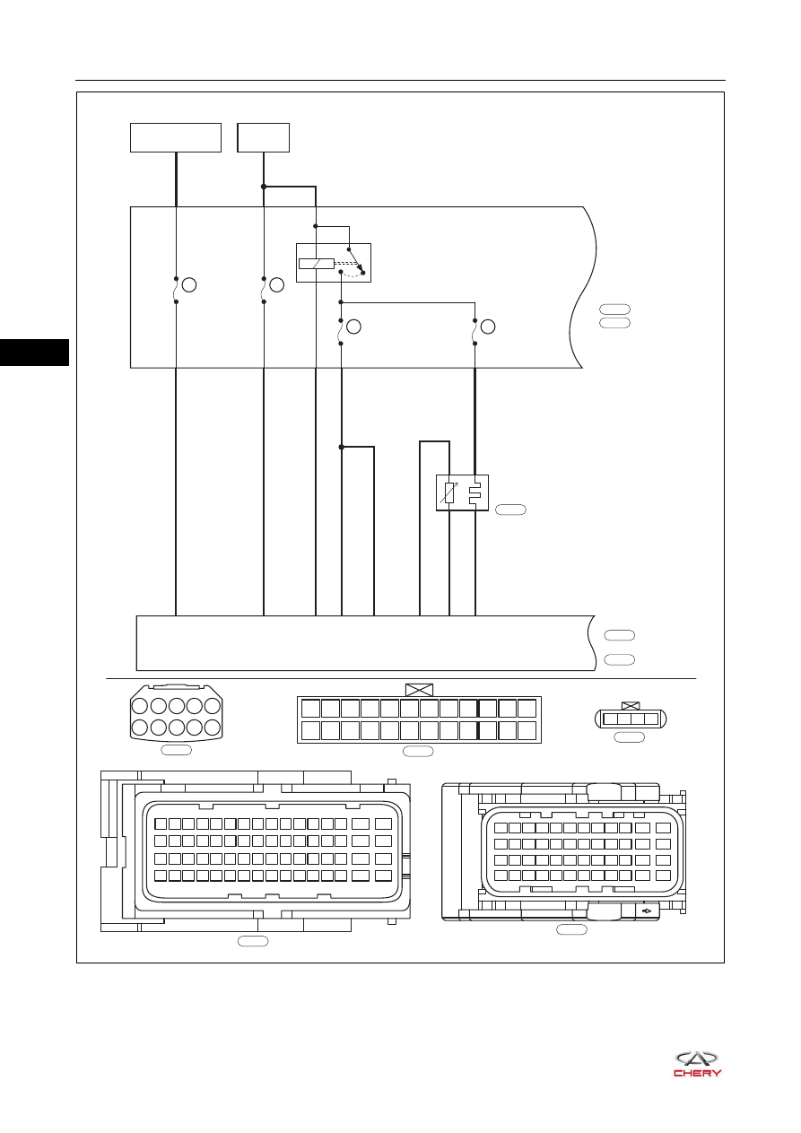
ET21065002
BATTERY
ECM
MAIN
RELAY
10A
EF19
10A
EF17
10A
EF40
10A
EF39
A2
F14
2-20
RL
A4
2-35
L
2-5
Br
A6
A7
2-15
2-16
RR
R
R
RL
YL
GL
86
87
85
30
1-40
1-9
3
1-16
1
4
2
UPSTREAM
OXYGEN
SENSOR
ENGINE
COMPARTMENT
FUSE AND
RELAY BOX
IGNITION SWITCH
ON OR START
A1
A2
A3
A4
A5
A6
A7
A8 A9 A10
F12
F24
F11
F23
F10
F22
F9
F21
F8
F20
F7
F19
F6
F18
F5
F17
F4
F16
F3
F15
F2
F14
F1
F13
1
2
3
4
Gr
E-076
W
E-069
E-084
B
E-084
E-076
E-069
B
E-033
B
E-035
49 50 51
63
64
15
16
31
32
47
48
33 34 35
17 18 19
1
2
3
52 53 54 55 56 57 58 59 60 61 62
36 37 38 39 40 41 42 43 44 45 46
20 21 22 23 24 25 26 27 28 29 30
4
5
6
7
8
9 10 11 12 13 14
ECM-2
ECM-1
E-033
E-035
37 38 39 40 41 42 43 44 45 46
47
48
25 26 27 28 29 30 31 32 33 34
35
36
13 14 15 16 17 18 19 20 21 22
23
24
1
2
3
4
5
6
7
8
9 10
11
12