Chery Tiggo. Manual - part 290


  Index      Chery     Chery Tiggo - service repair manual 2009 year


Search            


Content   ..  288  289  290  291   ..


Chery Tiggo. Manual - part 290


• Turn ignition switch on, with the scan tool, view and erase stored DTCs in the TCM.

• Start engine and warm it to normal operating temperature, then select ⬙D⬙ position.

• Drive the vehicle in 1st, 2nd, 3rd and 4th gears.

• With the scan tool, select view DTC and data stream.

• If the DTC is detected, the DTC condition is current. Go to Diagnostic Procedure - Step 1.

• If the DTC is not detected, the DTC condition is intermittent (See Diagnostic Help and Intermittent DTC Trou-

bleshooting in Section 08 Transaxle & Transfer Case for more information).

NOTE :
Checking the automatic transaxle fluid quality and fluid level is the most basic check of the automatic transaxle. The
fluid check is also an important inspection to determine if the transaxle will need to be disassembled.

CAUTION:
The burnt scent of ATF fluid indicates that the transaxle fluid is contaminated. The tiny particles in
the fluid pan indicate that the transaxle is worn out and it will be necessary to overhaul the trans-
axle.

NOTE :
While performing electrical diagnosis & testing, always refer to the electrical schematics for specific circuit
and component information.

Diagnostic Procedure

1.

CHECK FLUID QUALITY AND FLUID LEVEL AND DTC

• Drive the vehicle, until the ATF reaches operating temperature (70° - 80°C).

• Park the vehicle on level ground.

• Shift the gear selector lever to all gear positions once, then shift to gear “N”.

• Clean and check the outside of the dipstick and remove the dipstick to check the fluid level.

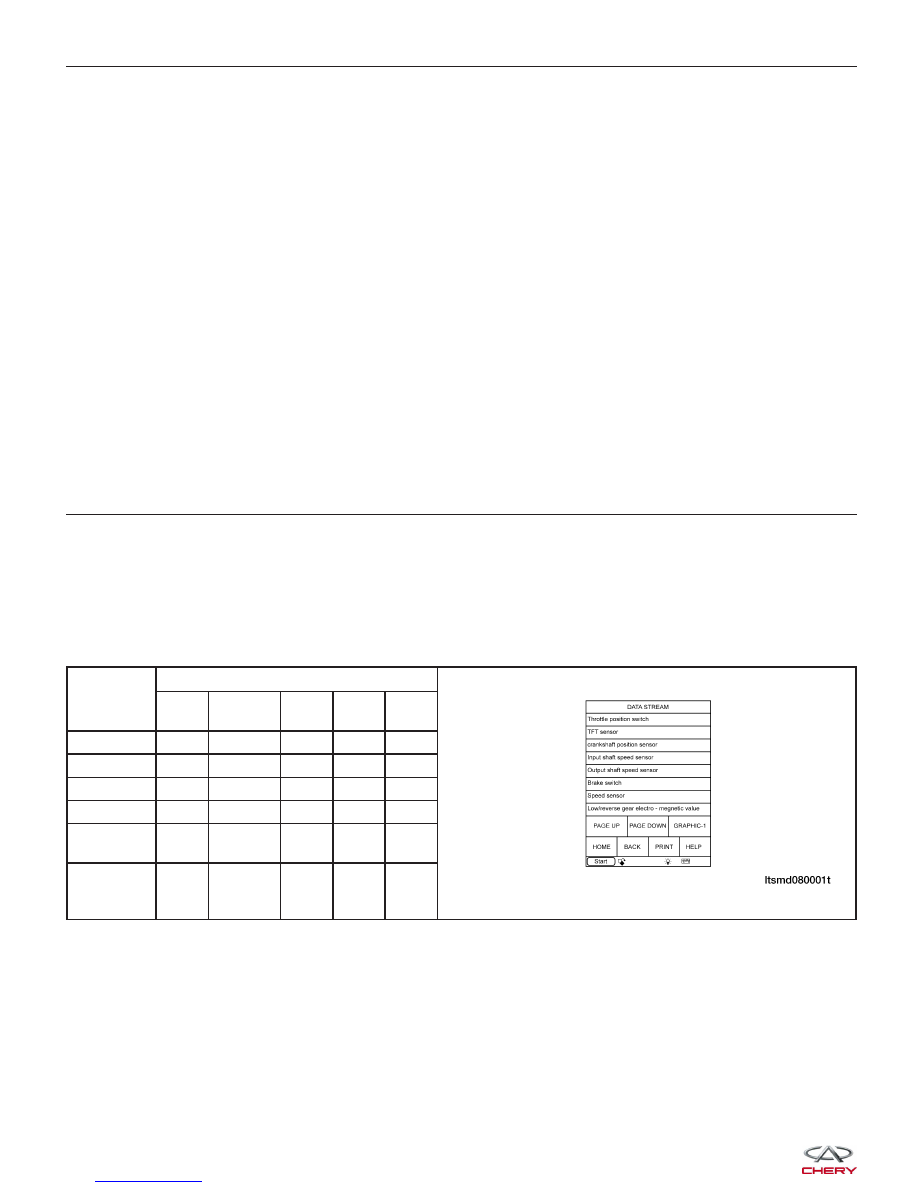
• With the scan tool, select view DTC and data stream for A/T.

• Start the engine.

• Monitor the value of the gear position as indicated in the following table while driving:

GEAR

POSITION

ELECTRO-MAGNETIC VALVE

L/R

GEAR

2

UD

OD

DCC

(REF)

Gear 1

Off

On

Off

On

Off

Gear 2

On

Off

Off

On

On

Gear 3

On

Off

Off

Off

On

Gear 4

On

Off

On

Off

On

Reverse

gear

Off

On

On

On

Off

Neutral

gear/

Parking

Off

On

On

On

Off

Is DTC 22 or 23 present?

Yes

>>

If DTC 22 present, see diagnostic procedure for DTC 22 in 08 - Transaxle & Transfer Case
If DTC 23 present, see diagnostic procedure for DTC 23 in 08 - Transaxle & Transfer Case.

No

>>

Go to the next step.

DIAGNOSIS & TESTING


2.

HYDRAULIC TEST

• Preheat the fluid from engine to transaxle to 80° - 100°C.

• Lift the vehicle until the wheels can rotate freely.
• Connect the special fluid pressure gauge on the

fluid pressure test port.

TEST

PORT

1

2

3

4

5

6

7

Fluid

pressure

test port

name

2nd (Gear

2 Brake)

fluid

pressure

UD (Low

Speed

Clutch)

fluid

pressure

L/R

(Low/

Reverse

Gear

Brake)

fluid

pressure

DA (Damper

Clutch

Engagement)

fluid

pressure

DR (Damper

Clutch

Disengagement)

fluid pressure

RV

(Reverse

Gear

Clutch)

fluid

pressure

OD

(Overdrive

Clutch)

fluid

pressure

DIAGNOSIS & TESTING

LTSMD080018

08


MEASURE STATUS

STANDARD FLUID PRESSURE KPA (PSI)

GEAR LEVER

POSITION

GEAR

POSITION

ENGINE

SPEED

(RPM)

DECELERATION

CLUTCH

PRESSURE

REVERSE

GEAR

CLUTCH

PRESSURE

OVERDRIVE

CLUTCH

PRESSURE

LOW/

REVERSE

GEAR

CLUTCH

PRESSURE

SECONDARY

BRAKE

PRESSURE

TORQUE

CONVERTER

PRESSURE

P

-

2,500

-

-

-

310 - 390

(45-56)

-

250 - 390 (36

- 56)

R

Reverse Gear

2,500

-

1,270 - 1,770

-

1,270 - 1,770

-

500 - 700 (73

- 101)

N

Neutral Gear

2,500

-

-

-

310 - 390 (45

- 56)

-

250 - 390 (36

- 56)

D

Gear 1

2,500

1,010 - 1,050

(146 - 152)

-

-

1,010 - 1,050

(146 - 152)

-

500 - 700 (73

- 101)

Gear 2

2,500

-

-

-

-

1,010 - 1,050

(146 - 152)

500 - 700 (73

- 101)

Gear 3

2,500

590 - 690 (85 -

100)

-

590 - 690

(85 - 100)

-

-

450 - 650 (65

- 94)

Gear 4

2,500

-

-

590 - 690

(85 - 100)

-

590 - 690 (85

- 100)

450 - 650 (65

- 94)

• In accordance with the shown status of standard fluid pressure measurement table, measure the fluid pressure

of each measurement port. The measurement of each port should be within the standard range.

• If some measurement values is beyond the standard range, please refer to the fluid pressure measurement and

diagnosis table for causes.

Is the check result normal?

Yes

>>

Go to step 5 for disc or plate abrasion.

No

>>

Go to the next step.

3.

CHECK VALVE BODY ASSEMBLY AND FLUID PUMP AND PIPELINE

• Turn the ignition switch off.

• Disassemble and repair F4A4 automatic transaxle assembly (See Automatic Transaxle Removal & Installation in

Section 08 Transaxle & Transfer Case).

• Check valve body and fluid pump and pipeline.

Is the check result normal?

Yes

>>

Go to the next step.

No

>>

Replace damaged components and low speed clutch and 2nd gear brake clutch for low pressure

burned.

4.

COMPRESSED AIR TEST

• Check low speed clutch system: Low speed clutch piston should be active and maintain pressure when com-

pressed air is applied to the fluid hole.

• Check 2nd gear brake clutch system: 2nd gear brake clutch piston should be active and maintain pressure

when compressed air is applied to the fluid hole.

Is the check result normal?

Yes

>>

Go to the next step for disc or plate abrasion.

No

>>

Replace all damaged components and low speed clutch and 2nd gear brake clutch.

DIAGNOSIS & TESTING


5.

CHECK LOW SPEED CLUTCH SYSTEM

• Check low speed clutch system:

− Check low speed clutch plate
− Check low speed clutch disc
− Snap ring
− Clutch reaction disc
− D-Ring
− Spring retainer
− Low speed clutch piston
− Low speed clutch drum

Is the check result normal?

Yes

>>

Go to the next step.

No

>>

Replace the damaged components.

6.

CHECK 2ND GEAR BRAKE SYSTEM

• Check 2nd gear brake system:

− Check 2nd gear brake plate
− Check 2nd gear brake disc
− Central support
− Snap ring
− Clutch reaction disc
− Spring retainer
− 2nd gear brake piston

Is the check result normal?

Yes

>>

Go to the next step.

No

>>

Replace the damaged components.

7.

CHECK DTC

• Assemble all disassembled components.

• Install the transaxle assembly (See Automatic Transaxle Removal & Installation in Section 08 Transaxle &

Transfer Case).

• Fill the transaxle with new ATF:

− Fill the ATF from the fill tube.
− Reinstall the hose connector disassembled in step 1 and reinstall the dipstick (clean the dipstick before

installing).

− Shift the gear selector lever to each gear position and then shift to gear “N”.
− Drive the vehicle until the ATF reaches operating temperature (70° - 80°C) and re-check the fluid level. The

fluid level must be within the HOT range of dipstick.

− Reinstall the dipstick into the transaxle.
− With the X-431 scan tool, read TCM DTCs.
− Refer to

⬙DTC Confirmation Procedure⬙.

Is DTC 42 present?

Yes

>>

Replace the TCM.

No

>>

The system is now operating properly.

DIAGNOSIS & TESTING

08


Content   ..  288  289  290  291   ..