Chery Tiggo. Manual - part 285


  Index      Chery     Chery Tiggo - service repair manual 2009 year


Search            


Content   ..  283  284  285  286   ..


Chery Tiggo. Manual - part 285


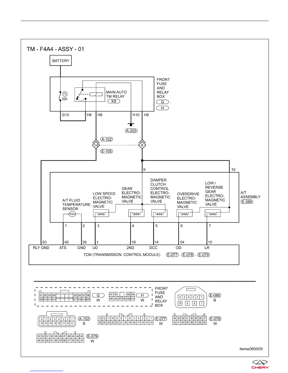
34 - Overdrive Solenoid Circuit Malfunction

DIAGNOSIS & TESTING

LTSMW080005T


On Board Diagnostic Logic
  Self-diagnosis detection logic.

DTC NO.

DTC

DEFINITION

DTC

DETECTION

CONDITION

DTC SET CONDITION

POSSIBLE

CAUSES

34

Overdrive

solenoid circuit

malfunction

Vehicle is driving


The Transaxle Control Module

(TCM) will set this DTC when the TCM
detected an improper voltage drop
when it tries to operate the solenoid
valve.
  If the DTC was set, then the A/T will
be locked in 3rd gear (D gear).


Solenoid

  Harness or
connectors (The
sensor circuit is
open or shorted)

TCM

DTC Confirmation Procedure:

Before performing the following procedure, confirm that battery voltage is more than 12 V.

Connect the X-431 scan tool to the Data Link Connector (DLC) - use the most current software available.
After connection, press POWER key to start X-431.
Turn ignition switch on, with the scan tool, view and erase stored DTCs in the TCM.
Start engine and warm it to normal operating temperature, then select D position.
Drive the vehicle in 1st, 2nd, 3rd and 4th gears.
With the scan tool, select view DTC and data stream.
If the DTC is detected, the DTC condition is current. Go to Diagnostic Procedure - Step 1.
If the DTC is not detected, the DTC condition is intermittent (See Diagnostic Help and Intermittent DTC Trou-
bleshooting in Section 08 Transaxle & Transfer Case for more information).

NOTE :
While performing electrical diagnosis & testing, always refer to the electrical schematics for specific circuit
and component information.

DIAGNOSIS & TESTING

08


Diagnostic Procedure

1.

CHECK A/T SOLENOID SIGNAL

• With the scan tool, select view DTC and data stream for A/T.

• Start the engine.

• Monitor the value of the gear position as indicated in the following table while driving:

GEAR

POSITION

ELECTRO-MAGNETIC VALVE

L/R

GEAR

2

UD

OD

DCC

(REF)

Gear 1

Off

On

Off

On

Off

Gear 2

On

Off

Off

On

On

Gear 3

On

Off

Off

Off

On

Gear 4

On

Off

On

Off

On

Reverse

gear

Off

On

On

On

Off

Neutral

gear/

Parking

Off

On

On

On

Off

Is the check result normal?

Yes

>>

The condition that caused this DTC is intermittent (See Diagnostic Help in Section 08 Transaxle &

Transfer Case).

No

>>

Go to the next step.

2.

ACTUATE TEST

• With X-431, perform the solenoid actuate test.

• The solenoid should be heard.

Is the check result normal?

Yes

>>

Go to step 7.

No

>>

Go to the next step.

DIAGNOSIS & TESTING


3.

CHECK OVERDRIVE ELECTRO-MAGNETIC VALVE

• Stop vehicle and turn ignition switch off.

• Disconnect A/T assembly connector.

NUMBER

SOLENOID

WIRE COLOR

1

Low Speed

Electro-Magnetic

Valve (UD)

White / Red

2

2nd Gear

Electro-Magnetic

Valve (2nd)

Yellow / Red

3

Damp clutch

system control

Electro-Magnetic

Valve (DCC)

Brown / Yellow

4

Overdrive

Electro-Magnetic

Valve (OD)

Blue / Yellow

5

Low/reverse

Gear Electro-

Magnetic Valve

(L/R)

Black / Red

• Check OD solenoid resistance as shown in the following table:

A/T

ASSEMBLY

TERMINAL

LOW/

REVERSE

GEAR

ELECTRO-

MAGNETIC

VALVE

(L/R)

OVERDRIVE

ELECTRO-

MAGNETIC

VALVE

(OD)

2ND GEAR

ELECTRO-

MAGNETIC

VALVE

(2ND)

LOW

SPEED

ELECTRO-

MAGNETIC

VALVE

(UD)

7 - 10

6 - 10

4 - 9

3 - 9

Resistance

(23°C

7.3 - 0.69

Is the check result normal?

Yes

>>

Replace the OD Electro-Magnetic Valve with a known good one.
With X-431, perform the solenoid actuate test.
− If the solenoid can be heard, the system is normal.
− If the solenoid can’t be heard, go to the next step.

No

>>

Replace the damaged OD Electro-Magnetic Valve.

DIAGNOSIS & TESTING

08


Content   ..  283  284  285  286   ..