Chery Tiggo. Manual - part 263
• #: Operating solenoid
Is the check result normal and DTC not present?
Yes
>>
The condition that caused this DTC is intermittent (See Diagnostic Help in Section 08 Transaxle &
Transfer Case).
No
>>
Go to the next step.
2.
ACTUATE TEST
• With X-431, perform the solenoid actuate test.
• Watch, listen and monitor the shift lock solenoid condition and verify the shift lock solenoid works correctly and
the solenoid should be heard when actuate shift lock solenoid valve.
Is the check result normal?
Yes
>>
Go to step 7.
No
>>
Go to the next step.
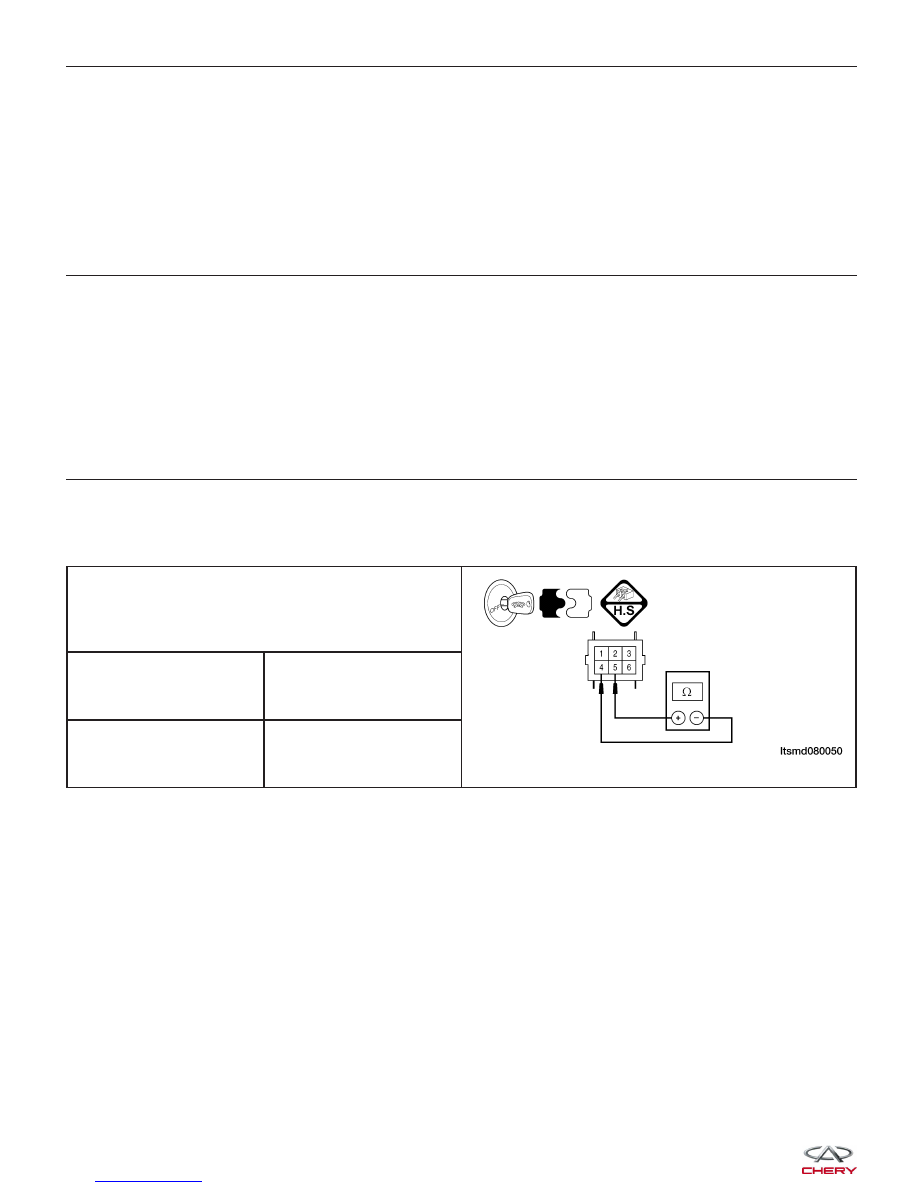
3.
CHECK SHIFT LOCK SOLENOID VALVE RESISTANCE
• Turn the ignition switch off.
• Disconnect shift lock solenoid valve connector C-027.
• Check shift lock solenoid valve resistance as shown in the following table:
SHIFT LOCK SOLENOID VALVE RESISTANCE
BASED ON TRANSAXLE TEMPERATURE
Temperature
Resistance
23°C
36 - 44
⍀
Is the check result normal?
Yes
>>
Replace the shift lock solenoid valve with a known good one.
With X-431, perform the solenoid actuate test.
− If the solenoid can be heard, go to step 7.
− If the solenoid can’t be heard, go to the next step.
No
>>
Replace the shift lock solenoid for a mechanical problem.
DIAGNOSIS & TESTING