Chery Tiggo. Manual - part 133


  Index      Chery     Chery Tiggo - service repair manual 2009 year


Search            


Content   ..  131  132  133  134   ..


Chery Tiggo. Manual - part 133


ECM Connector Pin-Out Table
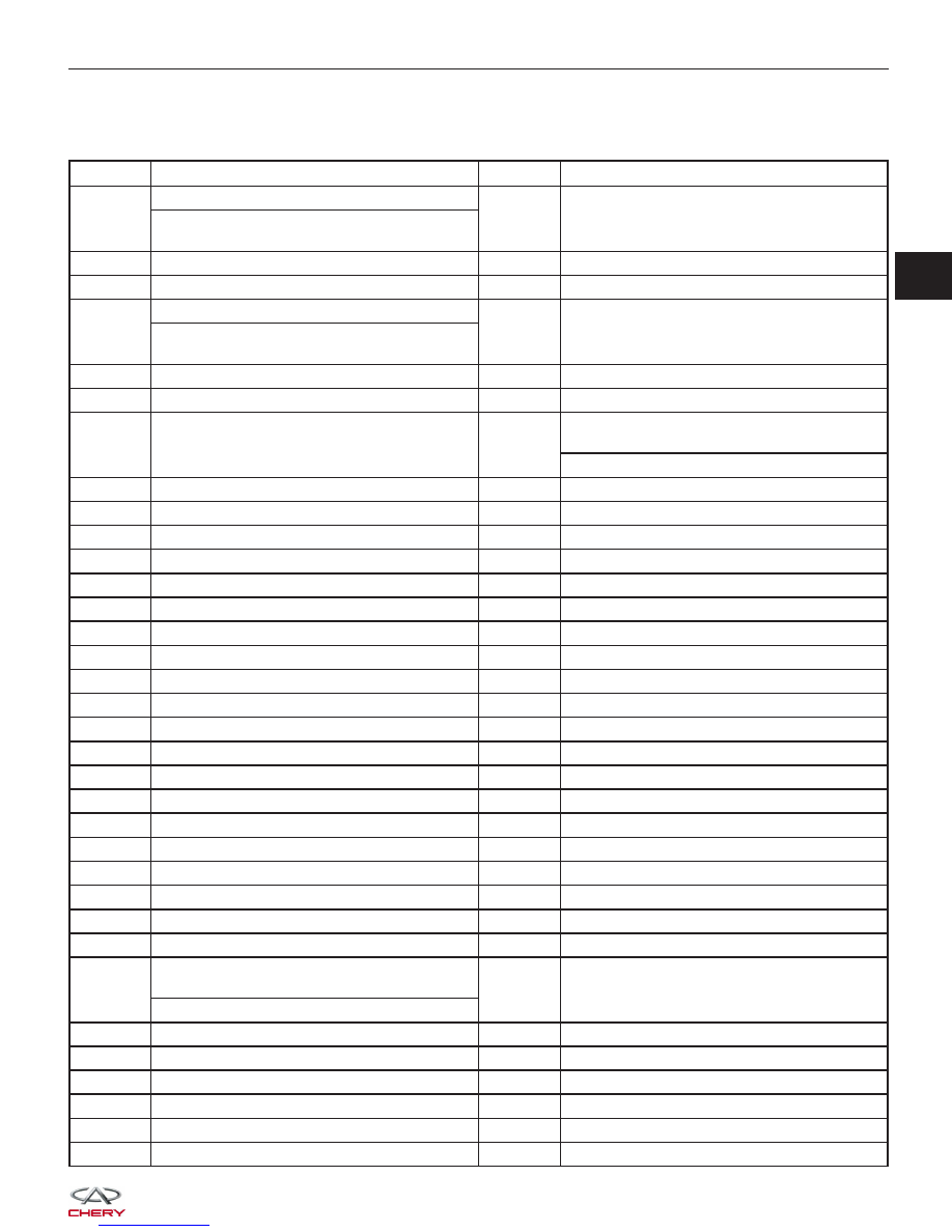
ECM PIN-OUT TABLE

PIN

CIRCUIT IDENTIFICATION

PIN

CIRCUIT IDENTIFICATION

1

(With EOBD)

42

Intake Air Temperature Sensor

Upstream Oxygen Sensor Heater (Without

EOBD)

2

Ignition Coil 2

43

-

3

GND (Ignition)

44

Switched Supply Voltage

4

(With EOBD)

45

Switched Supply Voltage

Downstream Oxygen Sensor Heater

(Without EOBD)

5

Ignition Coil 1

46

Canister Control Valve

6

Injector 2

47

Injector 4

7

Injector 3

48

Upstream Oxygen Sensor Heater (With

EOBD)

(Without EOBD)

8

Engine Speed Output

49

-

9

Coolant Temperature Output

50

Fan Relay Control

10

Fuel Consumption Output

51

GND (Signal)

11

EPC Lamp

52

-

12

Continuous Supply Voltage

53

GND (Signal)

13

Ignition Switch

54

Electronic Throttle Control Actuator

14

EMS Relay (Main Relay)

55

Downstream Oxygen Sensor

15

Crankshaft Position Sensor

56

-

16

Accelerator Position Sensor

57

-

17

Sensor (GND)

58

Brake Switch

18

Upstream Oxygen Sensor

59

-

19

Knock Sensor 1

60

A/C Middle Pressure Switch

20

Knock Sensor 2

61

GND (Power)

21

Brake Switch

62

CAN-H

22

-

63

Switched Supply Voltage

23

Accelerator Sensor

64

Electronic Throttle Control Actuator

24

-

65

Electronic Throttle Control Actuator

25

-

66

Electronic Throttle Control Actuator

26

-

67

Electronic Throttle Control Actuator

27

Injector 1

68

Fan Relay Control 2

28

Downstream Oxygen Sensor Heater (With

EOBD)

69

Air Compressor Relay

(Without EOBD)

29

-

70

Fuel Pump Relay

30

-

71

Diagnostic Link K

31

MIL Lamp

72

-

32

Regulated Sensor Supply 3

73

Regulated Sensor Supply 2

33

Regulated Sensor Supply 1

74

-

34

Crankshaft Position Sensor

75

A/C Stand By

GENERAL INFORMATION

03


PIN

CIRCUIT IDENTIFICATION

PIN

CIRCUIT IDENTIFICATION

35

Sensor (GND)

76

Power Steering Switch

36

Sensor (GND)

77

Headlamp Switch

37

Air Flow Sensor

78

Sensor (GND)

38

Electronic Throttle Control Actuator (Position

Sensor)

79

Camshaft Position Sensor

39

Engine Coolant Temperature Sensor

80

GND (Power)

40

Accelerator Pedal Position Sensor

81

CAN-L

41

-

GENERAL INFORMATION


DIAGNOSIS & TESTING

Diagnostic Help

1. Confirm that the malfunction is current and carry-out the diagnostic tests and repair procedures.

2. If the Diagnostic Trouble Code (DTC) cannot be deleted, it is a current fault.

3. Use a digital multimeter to perform voltage readings on the Electronic Fuel Injection (EFI) system.

4. Program the vehicle Immobilizer control module whenever the Engine Control Module (ECM) is replaced.

5. The scan tool connects to the Data Link Connector (DLC) and communicates with the ECM.

6. If the failure is intermittent perform the following:

• Check for loose connectors.

• Look for any chafed, pierced, pinched, or partially broken wires.

• Monitor the scan tool data relative to this circuit and wiggle test the wiring and connectors.

• Look for the data to change or for the DTC to reset during the wiggle test.

• Look for broken, bent, pushed out or corroded terminals.

• Inspect the sensor and mounting area for any condition that would result in an incorrect signal, such as

damage or foreign material.

7. Remove the ECM from the troubled vehicle and install in a new vehicle and test. If the DTC can not be deleted,

the ECM is malfunctioning. If the DTC can be deleted, return the ECM to the original vehicle.

Ground Inspection

Ground connections are very important to the proper operation of electrical and electronic circuits. Ground connec-
tions are often exposed to moisture, dirt and other corrosive elements. The corrosion (rust) can become an unwanted
resistance. This added resistance can alter the way a circuit works.

Electronically controlled circuits are very sensitive to proper grounding. A loose or corroded ground can drastically
affect an electronically controlled circuit. A poor or corroded ground can effect the circuit. Perform the following when
inspecting a ground connection:

1. Remove the ground bolt or screw.

2. Inspect all mating surface for tarnish, dirt, rust, etc.

3. Clean as required to assure good contact.

4. Reinstall bolt or screw securely.

5. Inspect for

⬙add-on⬙ accessories which may be interfering with the ground circuit.

6. If several wires are crimped into one ground eyelet terminal, check for proper crimps. Make sure all of the wires

are clean, securely fastened and providing a good ground path. If multiple wires are crimped to one eyelet, make
sure no excess wire insulation has been crimped creating a bad ground.

Electronic Throttle Control Actuator Self-Learning Operation Introduction

EPC Lamp Control Strategy

The EPC lamp will be on for a few seconds and turn off after the ignition switch is turned on and the engine is not
running. After the engine started, the EPC lamp will go off if the DTC is not existent in ECM. If the internal self-check
failed, the EPC lamp will continue to light.

Electronic Throttle Control Actuator Self-Learning Condition

• Engine stopped and the ignition switch is on.

• Vehicle speed is 0 km/h.

• The Engine Coolant Temperature (ECT) is between 5.25°C and 100.5°C.

• The intake air temperature is more than 5.25°C.

• The accelerator pedal fully released.

• Battery voltage is more than 12 V.

Electronic Throttle Control Actuator Self-Learning Operating Procedure

Turn the ignition switch on for 10 seconds, then turn the ignition switch off. During the procedure, do not operate any
other components.

03


Self-Learning Components

Perform the self-learning process when the following repairs have been made:

• Replaced the ECM

• ECM which was disconnected and reconnected

• Replaced the Accelerator Pedal

• Replaced the Electronic Throttle Control Actuator

Self-Learning Operating Procedure

Turn the ignition switch on for 10 seconds, then turn the ignition switch off. During the procedure, do not operate any
other components.

Self-Learning Condition

The self-learning condition as the

⬙Electronic Throttle Control Actuator Self-Learning Condition⬙.

CAUTION:
Make sure that the Electronic Throttle Control Actuator self-learning process lasts for at least 10
seconds according to the Electronic Throttle Control Actuator self-learning condition. If the self-
learning process fails, the engine can’t be started or the EPC lamp will be on. If this condition
occurs, perform the Self-Learning operating again after the DTCs be erased in ECM.

Diagnostic Tools

• Scan Tool X-431

• Engine Analyzer KES-200

• Digital Multimeter

• Jumper Wire

DIAGNOSIS & TESTING


Content   ..  131  132  133  134   ..