Chery Tiggo. Manual - part 5


  Index      Chery     Chery Tiggo - service repair manual 2009 year


Search            


Content   ..  3  4  5  6   ..


Chery Tiggo. Manual - part 5


DIAGNOSING ELECTRICAL FAILURES

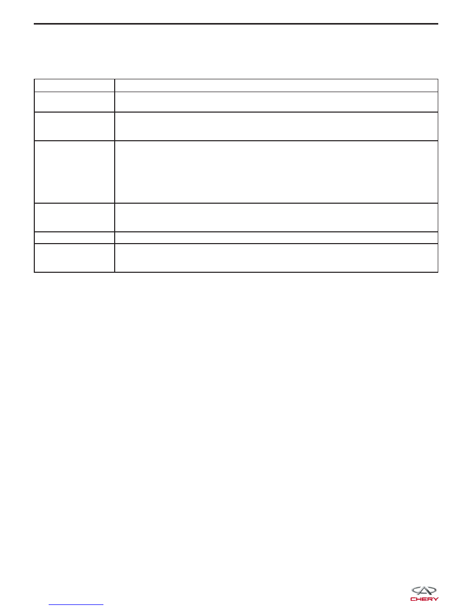
Performing Efficient Electrical Circuit Diagnosis and Troubleshooting

STEP

DESCRIPTION

Step 1

Obtain detailed information about the conditions and the environment when the electrical
incident occurred.

Step 2

Operate the affected system, road test the vehicle if necessary.
Verify the parameter of the incident.
If the problem cannot be duplicated, refer to “Electrical Failure Simulation Tests”.

Step 3

Gather the proper diagnostic material including the following:

• Electrical Power Supply Routing Diagram

• System Operation Descriptions

• Applicable Service Manual Sections

• Check for any Service Bulletins

Identify where to begin diagnosis based upon your knowledge of the system operation
and the customer comments.

Step 4

Inspect the system for mechanical binding, loose connectors or wiring damage.
Determine which circuits and components are involved and diagnose using the Electrical
Power Supply Routing Diagram and Harness Layouts.

Step 5

Repair the circuit or replace the component as necessary.

Step 6

Operate the system in all modes. Verify the system functions properly under all conditions.
Confirm you have not inadvertently created an additional new incident during your
diagnosis or repair steps.

Electrical Circuit Simulation Tests

Often the symptom is not present when the vehicle is brought in for service. If possible, re-create the conditions
present at the time of the incident. Doing so may help avoid a No Trouble Found Diagnosis. The following illustrates
tests to simulate the conditions/environment under which the owner experiences an electrical incident.

The tests are broken into the seven following topics:

• Vehicle Vibration Test

• Heat Sensitive Test

• Freezing Test

• Water Intrusion Test

• Electrical Load Test

• Cold or Hot Start Up Test

• Voltage Drop Test

NOTE :
Always get a thorough description of the incident from the customer. It is important for simulating the conditions of
the problem.

Vehicle Vibration Test

The problem may occur or become worse while driving on a rough road or when the engine is vibrating (idle with A/C
on). In such a case, check for a vibration related condition. Refer to the following vehicle areas:

Connectors & Harness
• Determine which connectors and wiring harness would affect the electrical system you are inspecting. Gently

shake each connector and harness while monitoring the system for the incident you are trying to duplicate. This
test may indicate a loose or poor electrical connection.

NOTE :
Connectors can be exposed to moisture. It is possible for a thin film of corrosion to form on the connector terminals.
A visual inspection may not reveal this without disconnecting the connector. If the problem occurs intermittently, per-
haps the problem is caused by corrosion. It is a good idea to disconnect, inspect and clean the terminals on related
connectors in the system.


Sensors & Relays
• Gently apply a slight vibration to sensors and relays in the system you are inspecting. This test may indicate a

loose or poorly mounted sensor or relay.

Engine Compartment
• There are several reasons a vehicle or engine vibration could cause an electrical complaint. Some of the things

to check for are:

− Connectors not fully seated.
− Wiring harness not long enough and is being stressed due to engine vibrations or rocking.
− Wires laying across brackets or moving components.
− Loose, dirty or corroded ground wires.
− Wires routed too close to hot components.

• To inspect components under the hood, start by verifying the integrity of the ground connections (See Ground

Inspection described later). First, verify that the system is properly grounded. Then check for any loose connec-
tions by gently shaking the wiring or components as previously explained. Using the wiring diagrams, inspect
the wiring for continuity.

Behind The Instrument Panel
• An improperly routed or improperly clamped harness can become pinched during accessory installation. Vehicle

vibration can aggravate a harness which is routed along a bracket or near a mounting screw.

• An unclamped or loose harness can cause wiring to be pinched by seat components (such as slide guides)

during vehicle vibration. If the wiring runs under seating areas, inspect wire routing for possible damage or
pinching.

Heat Sensitivity Test

The customer’s concern may occur during hot weather or after the vehicle has sat for a short time. In such cases you
will want to check for a heat sensitive condition.

To determine if an electrical component is heat sensitive, heat the component with a heat gun or equivalent.

CAUTION:
Do not heat components above 60°C (140°F).

If the incident occurs while heat testing the component, replace or properly insulate the component as needed.

Freezing Test

The customer may indicate the incident goes away after the vehicle warms up (winter time). The cause could be
related to water freezing somewhere in the wiring/electrical system. There are two methods to check for this:

• The first method is to arrange for the owner to leave the vehicle overnight. Make sure it will get cold enough to

duplicate the complaint. Leave the vehicle parked outside overnight. In the morning, do a quick and thorough
diagnosis of those electrical components which could be affected.

• The second method is to put the suspect component into a freezer long enough for any water to freeze. Rein-

stall the part into the vehicle and check for a reoccurrence of the incident. If it occurs, repair or replace the
component as needed.

Water Intrusion Test

The incident may occur only during high humidity or in rainy/snowy weather. In such cases the incident could be
caused by water intrusion on an electrical part. This can be simulated by soaking the car or running it through a car
wash.

Electrical Load Test

The incident may be electrical load sensitive. Perform diagnosis with all accessories (including A/C, rear window
defogger, radio, fog lamps) turned on.

Cold or Hot Starting Test

On some occasions an electrical incident may occur only when the vehicle is started cold, or it may occur when the
vehicle is restarted hot shortly after being turned off. In these cases you may have to keep the vehicle overnight to
make a proper diagnosis.

DIAGNOSING ELECTRICAL FAILURES

01


Voltage Drop Test

Voltage drop tests are often used to find components or circuits which have excessive resistance. A voltage drop in
a circuit is caused by a resistance in the circuit during operation.

• Check the circuit using a Digital Multimeter (DMM).

• When measuring resistance with a DMM, remember that contact by a single strand of wire will give a reading

of 0 ohms. This would indicate a good circuit. When the circuit operates, this single strand of wire is not able
to carry the current. The single strand will have a high resistance to the current. This will be indicated as a
slight voltage drop.

• Unwanted resistance can be caused by the following:

− Undersized wiring (single strand example)
− Corrosion on switch contacts
− Loose wire connections or splices

Precautions For Handling Control Modules and Electrical Components

• Never reverse polarity of battery terminals.

• Only install components specified for the vehicle.

• Before replacing the control module, check the input and output and functions of the components.

• When disconnecting components:

− Do not apply excessive force when disconnecting a connector.
− If a connector is installed by tightening bolts, loosen mounting bolt, then remove it by hand.

• When connecting components:

− Before installing a connector, make sure the terminal is not bent or damaged, and then correctly connect it.
− When installing a connector by tightening bolts, tighten the mounting bolt until the painted area of the con-

nector becomes even with the surface.

• Do not apply excessive shock to the control module by dropping or hitting it.

• Be careful to prevent condensation in the control module due to rapid temperature changes and do not let

water or rain get on it. If water is found in the control unit, dry it fully and then install it in the vehicle.

• Be careful not to let oil get on the control module connector.

• Avoid cleaning the control module with volatile oil.

• When using a DMM, be careful not to let the test probes touch each other causing a short circuit. Prevent the

power transistor in the control module from being
shorted to damaging battery voltage.

• When checking input and output signals of the con-

trol module, use the specified test adapter (if
applicable).

DIAGNOSING ELECTRICAL FAILURES

LTSMD030028


How To Check Electrical Connectors

Many electrical problems are caused by faulty electrical connections or wiring. It is also possible for a sticking com-
ponent or relay to cause a problem. Before condemning a component or wiring assembly always, check the electrical
connectors for good continuity.

How To Probe Connectors

• Connector damage and an intermittent connection can result from improperly probing the connector during cir-

cuit checks.

• The probe of a DMM may not correctly fit the connector cavity. To correctly probe the connector, follow the pro-

cedures below using a “T” pin. For the best contact, grasp the “T” pin using an alligator clip.

Probing From Harness Side

• If the connector has a rear cover connector, remove the rear cover before probing the terminal.

• Do not probe waterproof connectors from the harness side. Damage to the seal between the wire and connec-

tor may result.

Probing From Terminal Side

• Female Terminal:

− Do not insert any object into the female connector that is bigger than the male terminal.

• Male Terminal:

− Carefully probe the contact surface of each terminal using a “T” pin. Do not bend terminal.

How To Check Proper Contact Spring Tension Of Terminal

• An enlarged contact spring of a terminal may create intermittent signals in the circuit.

• If an intermittent open circuit occurs, follow the procedure below to inspect for open wires and enlarged contact

spring of female terminal.

− Use a male terminal which matches the female terminal.
− Disconnect the suspected faulty connector and hold it terminal side up.
− While holding the wire of the male terminal, attempt to insert the male terminal into the female terminal.
− While moving the connector, check whether the male terminal can be easily inserted or not.

NOTE :
If the male terminal can be easily inserted into the female terminal, replace the female terminal.

DIAGNOSING ELECTRICAL FAILURES

01


Content   ..  3  4  5  6   ..