Chery S11 / Chery QQ. Manual - part 232
Chery QQ Maintenance Manual 465 EFI System
DTC 14 TPS
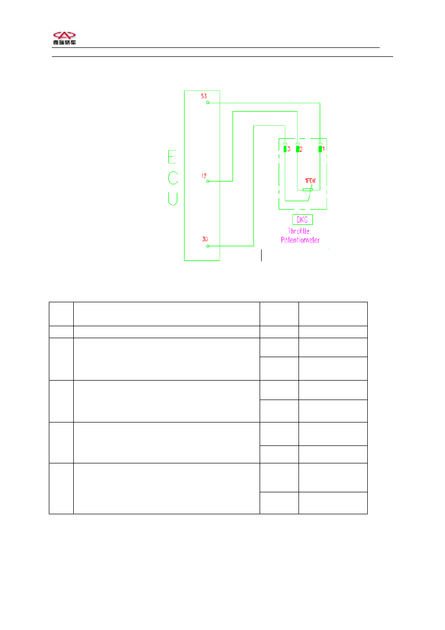
The diagram of TPS
No. Operation
steps Test
results
Next step
1
Turn on ignition key.
Next
Yes Next
2
Pull out connector of A/C evaporator temperature
sensor, measure if the volt between 2 pins is 5V
with multimeter.
No
5
Yes Next
3
Measure the resistance between pin (1) and (2) if
in 1.6 to 2.4k with multimeter.
No Replace
sensor
Yes Replace
sensor
4
Run slowly TPS from one end to another and
check any open or short between pin (1) and (3).
No Replace
ECU
Yes Repair
or
replace harness
5
Connect adaptor between ECU and harness,
check any open or short between pin 12 , 30 of
ECU and pin (1) and (2) of sensor with
multimeter.
No Replace
ECU
Note: For M1.5.4 with distributor, 5V voltage is supplied by pin 12 of ECU to TPS and Hall
sensor. If the DTC dislays when vehicle cannot be started, it cannot be clear DTC from TPS.
Please check if short in Hall sensor.
25