Chery S11 / Chery QQ. Manual - part 66


  Index      Chery     Chery S11 / Chery QQ - service repair manual


Search            


Content   ..  64  65  66  67   ..


Chery S11 / Chery QQ. Manual - part 66


Chery QQ Service Manual                              BCM Computer Control System   


Horn button wiring broken or loose contact 

thereof 

Repair or replace   

The sound of horn is 

low 

Insufficient charge of secondary cell 


Horn defective 

Interference between horn and direction 

indicator lamp 

Recharge or change the 

cell 

Replace 

Adjust 

After releasing the horn 

button, the horn would 

not stop 

Short in the horn button   


Replace 

Repair 


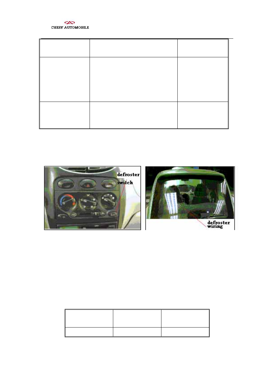
. Inspection and Repair of the Defrost System 

In figure defrost system is schematically shown. 


Schematic view of the defrost system 


1、Inspection of the conduction of the defroster switch 

As shown in the table, if it does not conform to the table, change the defroster 

switch. 

Inspection of the defroster switch 

Switch position 

Connection to the 

instrument  

Conductance 

Switch OFF 

No 

- 108 -   


Chery QQ Service Manual                              BCM Computer Control System   


Switch ON 

1-2 

Yes 


2、Inspection of defroster wiring 


While cleaning the window, wipe with soft cloth along the line, don’t damage the 

defroster wiring. Don’t use cleaning agent or cleaning device, otherwise the surface will 

be damaged. While inspecting the voltage, insert the negative probe in an end of the 

thermal fin, and push the wiring with finger as shown. 


Inspection of voltage 


Turn the start-up switch to ON, turn the defroster switch to ON, check the voltage at the 

midpoints of each wire as shown. If the wire is broken, there is a voltage of about 10v 

between the positive terminal of the meter and the midpoints of the wire, there is no 

voltage between earth and the midpoints of wire. 

Voltage State 

About 5V 

Normal 

About 10V or 0V

Broken 


Inspection of voltage of midpoint of the defroster wire 

- 109 -   


Chery QQ Service Manual                              BCM Computer Control System   


Connect the positive probe of the Voltage meter to positive terminal of the defroster, 

negative probe to the earth end. Press the positive probe on the hot wire and move it to 

the negative terminal. If the voltage springs from 0V to some V at some point, this point 

is the broken point, as shown in the figure. If the defroster wiring is not broken, at the 

positive terminal of the defroster wiring the volt meter shows 0V, and during the probe 

move to the other terminal, the voltage increases gradually to 12V. 


Detection of the broken point of the defroster wiring 

3、Repairing of the defroster wiring 


Eliminate the tool cleaning broken point with lubricating grease (wax) and organosilicon, 

during the repairing, attach adhesive tape on the both side of the defroster wiring. After 

mixing of the repairing agent, drop the repairing agent to the broken point in appropriate 

amount with electric brush. Remove the adhesive tape after few minutes, as shown in the 

figure 


Repairing of the defroster wiring 


. Inspection and Repair of Control System of Power Windows 

1. Operating mode of power windows 

- 110 -   


Chery QQ Service Manual                              BCM Computer Control System   


1

the function

 of 

power windows timer


After the start-up switch shut off, the power windows are operable within 30 seconds. 

If the doors are opened or closed in the period, the power windows can be operated 

within another 30 seconds. 

During lowering the power window, if an overload is detected, the power windows 

are operable within 30 secs. 

Within the last 6 seconds of above-mentioned period, if the door window switch is 

hold upwards for over 0.3 second, the door window then works in overloaded state to 

prevent that the door window stops in opened state. 

2)The function of power windows 

operating condition 

In the ON state of the start-up switch, after the start-up switch is turned off(the 

operating time of the power window timer is within 30s) 

operating progress 

The power window switch is actuated for over 0.3s, the door window rises and lowers 

automatically. During its operating, if the power window switch is actuated once again, 

the door window stops. 

stop conditions of the door windows 

A. If the current through the door window motor is higher than 14.5A+1A, the door 

window stops after 0.7s operating time. 

B. After operating for 6s (required by raising and lowering the door window), the 

operating stops. 

Re

ference: if raising or lowering not completed within 6s, check the overload current 

detecting function of door window motor or the installation of the door edging and door 

window regulator. 

3stepping mode power window 

Operating condition: the same as that of power windows. 

Within 0.3s, if power window switch is in its raising or lowering position, the 

door window operates in stepping mode with the step length of 0.5s. 

If raising and lowering switch is actuated in same direction N times within 0.3s, 

the door window operates for a period of (0.5xN)s. 

- 111 -   


Content   ..  64  65  66  67   ..