Chery S11 / Chery QQ. Manual - part 12


  Index      Chery     Chery S11 / Chery QQ - service repair manual


Search            


Content   ..  10  11  12  13   ..


Chery S11 / Chery QQ. Manual - part 12


Chery QQ Service Manual                                            Transmission System


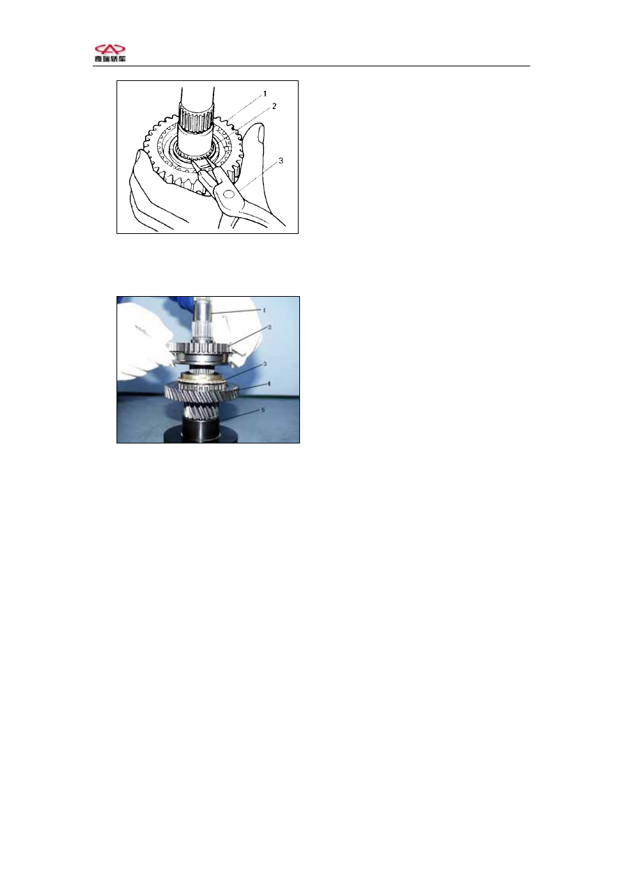
1- Hub sleeve outer race   

2- Snap ring   

3- Special tool


         Fig.3-33 
5. Remove the synchronizer assembly, 1st Synchronizer ring. 
6. Remove the 1st driven gear and needle roller bearing.   

1,  Output shaft  

2,  Hub sleeve  outer race  

3,  1st synchronizer ring  

4,  1st driven gear  

5,  Special tool  


          Fig.3-34 


Check and re-install: 

1.Clear up all the parts, check if there is anything abnormal, if necessary, change 
the used parts. 
2.If the synchronizer need repair, first check the clearance “a” between 

synchronizer ring and gear and the clearance between the angle and hub, and then 
decide if changed the used parts. 

-69-  


Chery QQ Service Manual                                            Transmission System


1- Gear   

2- Synchronizer ring   

         Fig.3-35 
 

 Standard 1.0~1.4mm 

 Clearance“a” 

 Use limit:0.5mm 

 
3. In order to keep lubricate smoothly, blow the oil away, be sure there is not any 

backup in the oil way.   


1- Output shaft   

2- 

Oil way


           Fig.3-36 
 
4. Install the synchronizer assembly , insert    3 pieces of synchronizer insert, and 

then install the spring according to the figure.   


-70-  


Chery QQ Service Manual                                            Transmission System


1- Snap ring   

2- 

Synchronizer insert 


3- Hub   

4- Hub sleeve outer race


Notice: 

   Synchronizer insert is not on the right direction. 
 Snap ring and synchronizer insert and synchronizer assembly, 5th 

synchronizer assembly compare is big. 

5.Install the output shaft bearing. 


1-Output shaft 

right

bearing 


2- Output shaft   

3- Special tool   

           Fig.3-38 
6.Spread lubricant on the needle roller bearing, and then install the 1st driven gear 

and 1st synchronizer ring. 


1-1st synchronizer ring 

2-2nd synchronizer ring 

                 Fig.3-39 

Notice: The width of 1st synchronizer ring synchronizer insert is smaller than the 
width of the 2nd synchronizer ring synchronizer insert. 
Width:

“b”  :8.2mm 

    “c”  :8.8mm 

-71-  


   The width of the 1st and 2nd      needle roller bearing is the same. 


Chery QQ Service Manual                                            Transmission System


7. Hammer the synchronizer assembly. 

Notice: 

 Use special  tool  support  right  output shaft ,avoid  bearing  holding 

race  destroy。 

 When installing the synchronizer assembly, keep the synchronizer insert and 

the synchronizer insert on the synchronizer assembly face to face.   

 After installation, check if the 1st gear turns smoothly. 


       Fig.3-40 
8. Spread lubricant on the snap ring and needle roller bearing, and then install the 

2nd synchronizer ring and 2nd driven gear. 


1-1st driven gear   

2- Synchronizer assembly 

3- Snap ring   

4- Needle roller bearing     

5-2nd synchronizer ring   

6-2nd driven gear 

1- Synchronizer assembly 

2-1st Synchronizer ring   

3-1st driven gear   

4- Right bearing   

5- Special tool   

6- Special tool   

7- Special tool   

         Fig.3-41 

Notice: Be sure the snap ring has been installed in the clitellum.   

9, Install the 3rd    driven gear and spacer.   

Notice: It is suggested that first install the 3rd    driven gear and spacer , secondly 
install the 4th driven gear, in this way, the output shaft will not bear too much 
pressure. 


-72-  


Content   ..  10  11  12  13   ..