Chery QQ6 (S21) / S12LHD. Manual - part 47


  Index      Chery     Chery QQ6 (S21) / S12LHD - service repair manual


Search            


Content   ..  45  46  47  48   ..


Chery QQ6 (S21) / S12LHD. Manual - part 47


14 

4.10 If the rear brake is found too tight during driving,   

adjust the length of push rod: Turn it in the cloclwise 

direction to eliminate the friction.   


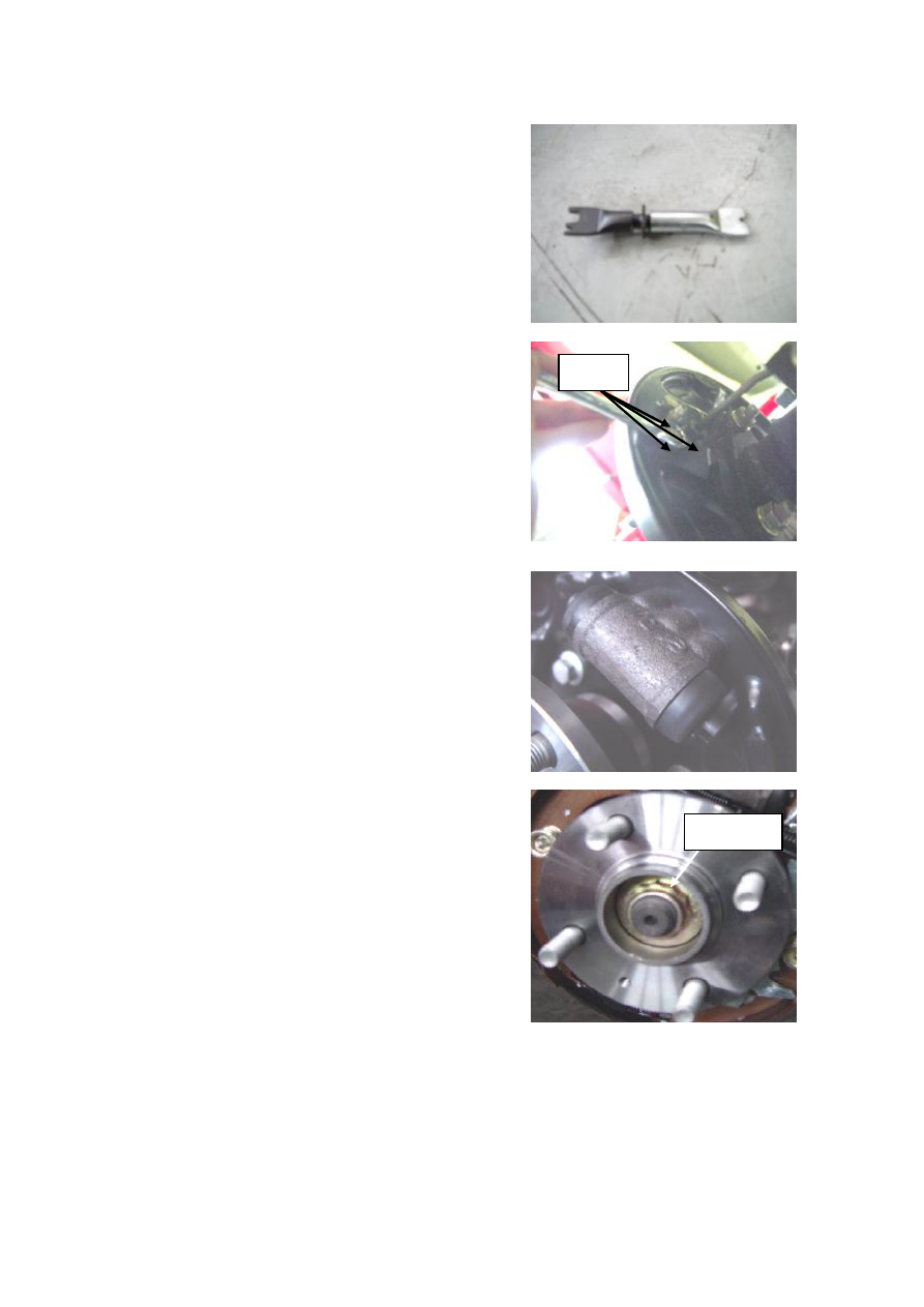
4.11 Remove three bolts as shown in the picture wit a 10# 

box wrench.   


1.12 Take off the brake wheel cylinder, and detach and   

check whether it is in good condition. 


4.13 If it is necessary to check the brake drum   

bearing, remove the lock nuts as shown in the   

picture with a 32# sleeve and a torque spanner,   

and take off the brake drum bearing.   

Torque: 250±10 N.m 


5. Installation Step 

Refer to Removal Step

Bolts 

Lock Nuts 

15 

IV. Adjustment and Replacement of Hand Brake 

1. System Composition Diagram 


1. Handle        2. Fixing Bolt        3. Control Cable        4. 5. Rear Right/Left Wheel Control Cable 

2. Preparation 

Tools: ratchet wheel, lug bar, 10#, 13#, 14#, 16# sleeve, 10#,   

13#, 14# box wrench, vice, torque spanner, right-angled screwdriver.   

3. Precautions 

3.1 Please wear necessary labor protection supplies to avoid accidents. 

3.2  When  carrying  out  disassembly  and  assembly  of  elastic  element,  avoid  the  bounce  that  will 

cause injury. 

3.3 If the hand brake is removed or reinstalled near the exhaust pipe, wait for a period of time until 

the temperature of exhaust pipe falls down to the normal value so as to avoid the injury.   

4. Removal/Installation Step 

4.1 Refer to the removal/installation step of rear brake, and   

loosen the hand brake control cable.   


T

R

ea

r R

igh
t B

ra

k

e A

ssy
 

T

R

ea

r L

e

ft 

B

ra

k

e

 A

ssy
 

16 

4.2 Remove the bolt here from the hand brake control cable   

fixed support with a 13# box wrench. 


4.3 Remove the other bolts from the hand brake control   

cable fixed support with a 10# box wrench or a 10# socket   

wrench.   


17 

4.4 Remove the hand brake control cable at the other side   

with the same method.   


4.5 Remove two fixing bolts from the driver’s seat with a   

16# socket wrench, and then take off the seat.   


4. 6 Remove all fix screws from the auxiliary instrument 

panel assy with a cross screwdriver, and then take off the   

auxiliary instrument panel assy. 


4.7 Remove two hand brake fixing bolts as shown in the 

picture with a 10# socket wrench. 


4.8 Loosen two control cable fixing screws with a 14# box 

Wrench, and then take off the guide plate. 


Guide 
Plate 


Content   ..  45  46  47  48   ..