Chery A15. Manual - part 290


  Index      Chery     Chery A15 - service repair manual


Search            


Content   ..  288  289  290  291   ..


Chery A15. Manual - part 290


(2) The measured value shall comply 
with requirements. 
 
IV. Differential bearing 
adjustment/adjusting washer 
Measure and adjust the preload on 
differential side gear during gearbox 
maintenance, especially after the 
replacement of the following 
components:  
Drive gear 
Clutch body 
Differential body 
Differential bearing 
(1) Unfix the bearing cover. 
(2) Press a new bearing outer ring into 
the clutch body outer casing. 
(3) Press a new bearing outer ring into 
the gearbox body.  
(4) Lubricate the differential bearing 
with gearbox oil. Fix the differential 
assembly onto the gearbox body. Fix the 
clutch bell housing onto gearbox. The 
screwing torque is 29N.m.  
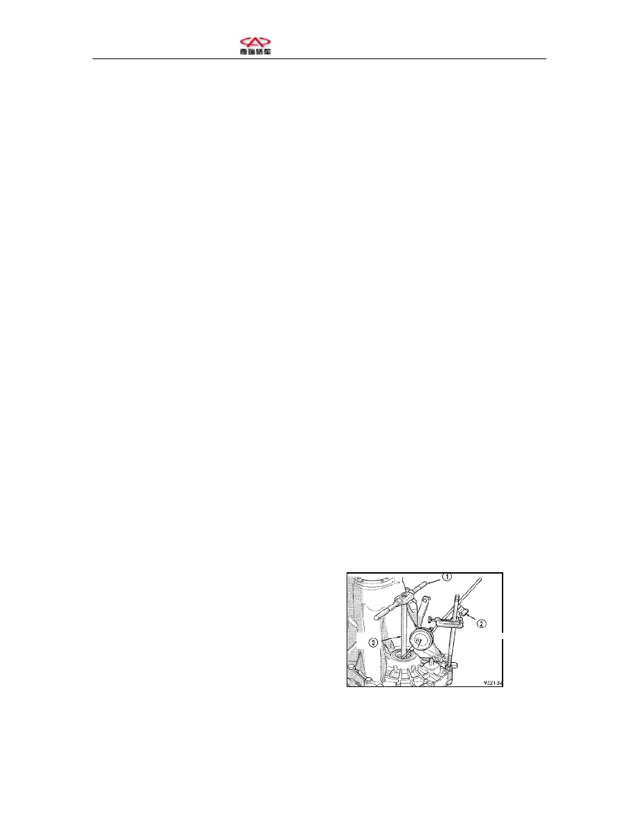
(5) Place the gearbox on the worktable 
with the clutch body outer casing facing 
down. Fix the dial indicator with C-
shape pliers.  
(6) Apply one moderate torque onto the 
differential with T spanners and turn the 
differential assembly to and fro until the 
bearing is set in place.  
Reset the dial indicator and read the 
axial clearance. Apply a certain load 
from front and rear while turning the 
differential assembly (Figure 85). 
Record the axial clearance.  
 
1-T spanner 
2-Dial indicator 
3-Special tool 


Figure 85 Checking the Differential 
Bearing Clearance and Measuring the 
Gasket Thickness 

 
(7) Use gaskets to the extent that they 
can come into close contact with the 
bearing.  
(8) Screw off the bolts in the gearbox 
body. Dismantle the clutch cover and 
differential roller bearing outer ring. Fix 
the selected gaskets (Step 7) and then 
push the roller bearing outer ring into the 
clutch body.  
(9) Install the clutch outer casing and 
screw the set bolts with a torque of 
26N.m.  
(10) Check the torque on the differential 
assembly with the special tool and 
torque spanner (Figure 86) and torque 
shall be 6-12 in.lbs. Fix one gasket 
0.05mm (0.002 inch) in thickness if the 
torque is too big and an even thicker 
gasket if the torque is too small.  


1-Torque spanner 
2-Special tool 


(11) Check the torque. Repeat (Step 10) 
until an appropriate torque is obtained. 
Place the gearbox onto the side plate and 
the gasket onto the flange. Fix clutch 
body outer casing onto the gearbox and 
screw the bolts with a torque of 29N.m. 


V. Unfixing the differential bearing 
cover 
(1) Unfix the differential assembly from 
the gearbox.  
(2) Fix Tool 4518 onto the differential 
bearing outer ring (Figure 87). 


Figure 86 Checking the Differential 
Bearing Torque 


1-Special tool 
2-Gearbox 


(3) Fix the tool (Figure 88). 


1-Gearbox casing 
2-Special tool 
3-Spanner 


(4) Screw tight the tool until the outer 
ring is unfixed from the gearbox casing.  
 
VI. Fixing the differential bearing 
cover 
(1) Place the bearing outer ring onto the 
gearbox casing.  
(2) Fix the bearing outer ring with the 
special tool.  
(3) Fix the differential bearing outer ring 
onto the drive casing with the tool. 


Figure 87 Fixing the Bearing Tool 


Figure 88 Fixing the tool. 


Section Six: Drainage and Adding of Gearbox Lubricating Oil 
 
The oil filler plug is located on the left 
of the gearbox differential (Figure 89). 
The car shall be located horizontally and 
oil level shall not be 4mm lower than the 
oil inlet.  


1-Oil filler rubber plug 
2-Left drive shaft oil seal 


The gearbox oil drain is located on the 
lower right corner of the gearbox 
differential (Figure 90).  
Screw tight the oil drain plug with a 
torque of 28N.m (250in.lbs). 


1-Oil drain plug 


Add an appropriate amount of gearbox 
oil into the gearbox and clean away the 
lubricating oil on the outer surface of the 
gearbox.  
Add ATF+4 hydraulic oil into the 
manual gearbox.  
2.4-2.7L 


Figure 89 Oil Filler Plug Location 


Figure 90 Oil Drain Plug Location 


Content   ..  288  289  290  291   ..