Chery A11. Manual - part 79
CHERY AUTOMOBILE CO., LTD Automatic Transmission Fault Diagnosis Manual
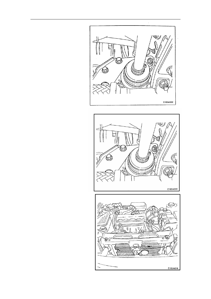
Front suspension
Disassembly procedure:
1. Remove
the
battery’s
negative terminal;
’s
nnecting
5.
ecting
on.
1.
nnecting the
e
2.
stall the bolt connecting the
ont suspension and the front
. Plug on the fan’s electric
.
nsmission on the whole
hicle.
ecial tool: J-28467-B engine
1.
2. Remove the cooling fan
electric terminal;
3. Remove the cooling fan;
4. Remove the bolt co
the front suspension and the
front cross-member;
Remove the bolt conn
the front suspension and the
transmissi
Assembly procedure:
Install the bolt co
front suspension and th
transmission;
In
fr
cross-member;
3. Install the cooling fan;
4
terminal;
5. Connect the battery’s negative
terminal
Disassembly of the automatic
tra
ve
Sp
hanger
Disassembly procedure:
Remove the battery;
2. Remove gearshift cable;
3. Take off the neutral positioning
switch’s terminal;
4. Remove the throttle cable;
5. Remove the cooler’s top cover;
63