Loader Bobcat 853, 853H. Manual - part 60


  Index      Bobcat     Bobcat 853, 853H loader - service manual


Search            


Content   ..  58  59  60  61   ..


Loader Bobcat 853, 853H. Manual - part 60


FAN GEARBOX (Cont’d)

Checking Backlash (Cont’d)

When the backlash is correct, install the seals, cap and
gear oil as follows:

Remove the bolts from the flanges and separate the two
housings.

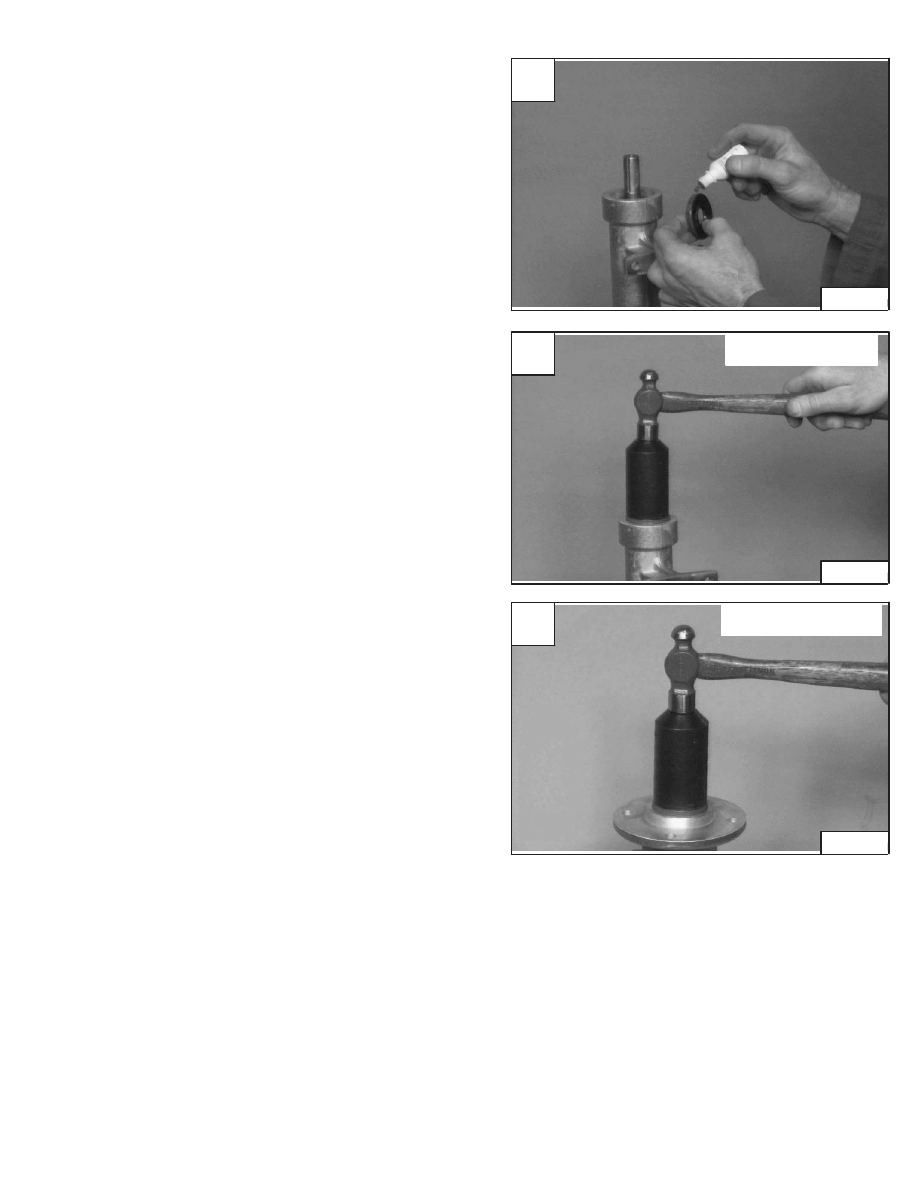
Put liquid adhesive (LOCTITE #242) on the outside
diameter of the seal(s) [A].

Install the seal(s) flush with the housing surface [B] & [C].

Clean any oil from the flange surface.

Install the long housing on the short housing flange.

Install the four bolts and part number tag.

Install and tighten the nuts to 25–28 ft.–lbs. (34–38 Nm)
torque.

A

P–03089

C

P–02986

SHORT HOUSING

853, 853H Loader

–7–29–

Service Manual

B

P–02985

LONG HOUSING

ENGINE

Removal And Installation

Raise the operator cab. (See Page 1–1.)

Disconnect the case drain hose (Item 1) [A] and drain the
hydraulic fluid into a container.

After the fluid is removed from the reservoir, loosen both
hose clamps and remove the hose (Item 2) [A] from the
reservoir and hydrostatic pump.

Loosen both hose clamps and remove the fuel vent hose
(Item 1) [B].

Loosen both hose clamps and remove the fuel fill hose
(Item 2) [B].

Remove the fan drive belt (Item 1) [C].

Loosen the hose clamps and remove the hose (Item 1)
[D] from the filter and the hydrostatic pump.

Never work on a machine with the lift arms up
unless the lift arms are secured by an approved
lift arm support device. Failure to use an
approved lift arm support device can allow the
lift arms or attachment to fall and cause injury
or death.

W–2059–0598

A

P–04856

2

1

C

P–04863

1

D

P–04861

1

–7–30–

853, 853H Loader

Service Manual

B

P–04855

2

1

ENGINE (Cont’d)

Removal And Installation (Cont’d)

Disconnect the wires (Item 1 & 2) [A] at the filter.

Disconnect the electrical harness connectors (Item 1)
[B].

Disconnect the ground wire  and harness clamp (Item 2)
[B].

NOTE: The electrical harness will be removed with

the engine.

Disconnect the hose (Item 1) [C] from the oil cooler.

Disconnect the hose (Items 2 & 3) [C] from the
hydrostatic pump.

When making repairs on hydrostatic and
hydraulic systems, clean the work area before
disassembly and keep all parts clean. Always
use caps and plugs on hoses, tubelines and
ports to keep dirt out. Dirt can quickly damage
the system.

I–2003–0284

A

CD–10993

1

2

C

P–04867

3

1

2

B

P–00883

1

2

1

853, 853H Loader

–7–31–

Service Manual

ENGINE (Cont’d)

Removal And Installation (Cont’d)

Disconnect the steering cables (Item 1) [A].

Installation:  See Page 3–1 for transmission neutral
adjustment.

Mark the high pressure hoses for correct installation.

Disconnect the four high pressure hoses (Item 2) [A] from
the pump.

Disconnect the high pressure hose (Item 1) [B] from the
hydraulic pump.

Disconnect the case drain filter hose (Item 1) [C] from the
pump.

Remove the bolt and nut (Item 2) [B] at the left front
engine mount.

Remove the bolt (Item 1) [D] at the right front engine
mount.

NOTE: The nut is held in the housing and will not

turn (Inset) [D].

Installation:  Tighten the mounting bolts and nuts to
90–100 ft.–lbs. (125–130 Nm) torque.

A

P–04878

2

2

1

C

P–04879

1

D

P–05008

1

P–04934

–7–32–

853, 853H Loader

Service Manual

B

P–04870

2

1


Content   ..  58  59  60  61   ..