Loader Bobcat 853, 853H. Manual - part 52


  Index      Bobcat     Bobcat 853, 853H loader - service manual


Search            


Content   ..  50  51  52  53   ..


Loader Bobcat 853, 853H. Manual - part 52


STARTER (Cont’d)

Disassembly And Assembly (Cont’d)

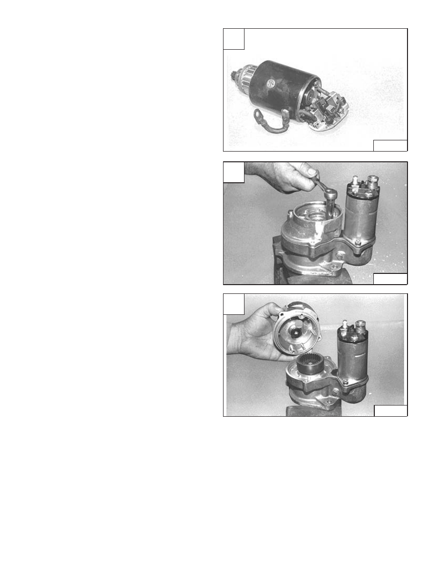
Remove the armature and brushes from the starter
housing [A].

Remove the bolts from the reduction gear housing [B].

Remove the reduction gear housing [C].

A

CD–08928

C

CD–08930

–6–20–

853, 853H Loader

Service Manual

B

CD–08929

STARTER (Cont’d)

Cleaning And Inspection

Use a brush and air pressure to clean the drive, field coils,
armature and starter housing.

NOTE: DO NOT use solvent to clean the drive

assembly. The solvent will remove the
lubricant and the drive will slip.

Check the following items:

Armature

Broken or burned insulation
Loose connections at commutator
Open or grounded circuits [A] & [B]
Worn shaft or bearings
Rough commutator

Brush Holders

Broken springs
Broken insulation
Spring tension

Field Coils

Broken or burned insulation
Electrical continuity
Brush connections

Drive Gears

Worn teeth
Tooth engagement

A

A–01995

853, 853H Loader

–6–21–

Service Manual

B

A–01994

STANDARD INSTRUMENT PANEL

Removal And Installation

Pry the rubber light mount loose from the operator cab
(both sides) [A].

Lower the light from the operator cab and locate the three
instrument panel mounting bolts (Item 1) [B] (both sides).

Remove the three mounting bolts (Item 1) [B].

Installation: Be careful not to overtighten the instrument
panel mounting bolts to prevent stripping the threaded
holes in the panels.

Pull the left instrument panel down and disconnect the
wire harness connectors from the panel. Remove the
panel [C].

Repeat steps [A] and [B]. Pull the right instrument panel
down and disconnect the wire harness connectors from
the panel. Remove the panel [D].

Reverse the removal procedure to install the instrument
panel.

A

P–03995

C

P–00962

D

P–00964

–6–22–

853, 853H Loader

Service Manual

B

P–03955

1

1

FRONT LIGHTS

Removal And Installation

The front lights are mounted in the upper corners of the
operator cab [A].

Pry the rubber light mount free from the operator cab [B].

Pull the light down and remove the three mounting bolts
(Item 1) [C] from the instrument panel.

Disconnect the front light connector from the instrument
panel. Remove the front light from the operator cab.

Reverse the removal procedure to install the front light.

A

P–03956

C

P–03955

1

1

853, 853H Loader

–6–23–

Service Manual

963 Service Manual #6724545–Electrical System Section Part 2 of 2

B

P–03995


Content   ..  50  51  52  53   ..