Loader Bobcat 853, 853H. Manual - part 5


  Index      Bobcat     Bobcat 853, 853H loader - service manual


Search            


Content   ..  3  4  5  6   ..


Loader Bobcat 853, 853H. Manual - part 5


OPERATOR CAB (Cont’d)

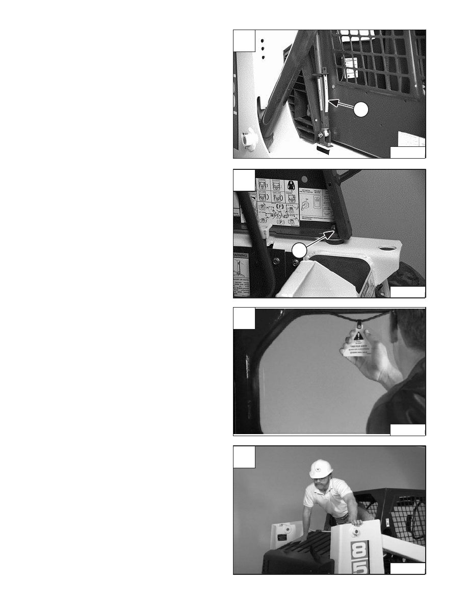
Lowering The Operator Cab

NOTE: Make sure the seat bar is fully raised or

lowered when lowering the cab.

Pull down on the bottom of the operator cab until it stops
at the latching mechanism.

Release the latching mechanism (Item 1) [A] and pull the
cab all the way down.

Install the plate and nut (Item 1) [B] (both sides).

Tighten the nuts to 40–50 ft.–lbs. (54–68 Nm) torque [B].

Emergency Exit

The front opening on the operator cab and rear window
provide exits.

To exit through the rear window, use the following
procedure:

Pull on the tag on the top of the rear window to remove the
rubber cord [C].

Push the rear window out of the rear of the operator cab.

Exit through the rear of the operator cab [D].

A

CD–15124

1

C

P–00660

D

P–00383

–1–10–

853, 853H Loader

Service Manual

B

CD–15126

1

SEAT BAR RESTRAINT SYSTEM

Description

The seat bar restraint system has a pivoting seat bar with

arm rests and has spring loaded interlocks for the lift and

tilt control pedals.

The operator controls the use of the seat bar. The seat bar

in the down position helps to keep the operator in the seat.

The interlocks require the operator to lower the seat bar

in order to operate the foot pedal.

When the seat bar is up, the lift and tilt pedals are locked

when returned to the NEUTRAL POSITION.

Inspecting The Seat Bar

Sit in the seat and fasten the seat belt. Engage the

parking brake. Pull the seat bar all the way down. Start the

engine. Operate each foot pedal to check both the lift and

tilt functions. Raise the lift arms until the bucket is about

2 feet (600 mm) off the ground.

Raise the seat bar. Try to move each foot pedal. Pedals

must be firmly locked in neutral position. There must be

no motion of the lift arms or tilt (bucket) when the pedals

are pushed.

Pull the seat bar down, lower the lift arms. Operate the lift

pedals. While the lift arms are going up, raise the seat bar

and the lift arms should stop.

Lower the seat bar, lower the lift arms and place the

bucket flat on the ground. Stop the engine. Raise the seat

bar and operate the foot pedals to be sure that the pedals

are firmly locked in the neutral position. Unbuckle the seat

belt.

Maintaining The Seat Bar

See the SERVICE SCHEDULE, Page 1–3 for correct

service interval.

Clean any debris or dirt from the moving parts [A] & [B].

Inspect the linkage bolts and nuts for tightness. The

correct torque is 25–28 ft.–lbs. (34–38 Nm).

Use a general purpose grease to lubricate the seat bar

pivot points at each side of the cab [A].

If the seat bar system does not function correctly, check

for free movement of each linkage part. Check for

excessive wear. Adjust pedal control linkage.

Replace parts that are worn or damaged. Use only

genuine Melroe replacement parts.

AVOID INJURY OR DEATH

The seat bar system must lock the lift and tilt

control pedals in neutral when the seat bar is

up. Service the system if pedals do not lock

correctly.

W–2105–1285

A

P–00384

Clean &

Lubricate

853, 853H Loader

–1–11–

Service Manual

B

P–01223

Clean

Pedal Lock

Shield

AIR CLEANER SERVICE

Replacing Filter Element

See the SERVICE SCHEDULE, Page 1–3 for the interval
to service the air cleaner system.

WITH CONDITION INDICATOR: Replace the large
(outer) filter element only when the red ring shows in the
window of the condition indicator (Item 1) [A].

NOTE:  Before replacing the filter element, push the

button on the condition indicator (Item 2) [A].
Start the engine. If the red ring does not
show, do not replace the filter element.

Replace the inner filter every third time the outer filter is
replaced or when the red ring still shows in the indicator
window after the outer filter has been replaced.

WITH BOSS

®

 OPTION: It is important to change the air

filter element only when the service codes (on the
BOSS

®

 option instrument panel) shows the symbols

[AF.2] [B].

Service the air cleaner as follows:

Remove the dust cover wing nut (Item 1) [C].

Remove the dust cover.

A

CD–15118

2

1

C

CD–15117

1

–1–12–

853, 853H Loader

Service Manual

B

MC–02042

AIR CLEANER SERVICE (Cont’d)

Replacing Filter Element (Cont’d)

Remove the wing nut (Item 1) [A] at the large air filter
element.

Remove the large filter element [B].

NOTE:  Make sure all sealing surfaces are free of dirt

and debris.

1. Replace the inner filter element every third time the

outer filter is replaced.

2. If the service codes show symbols, Page 8–1,

during full engine speed, replace the inner filter
element only after the outer filter element has been
changed.

Install the new filter element and washer and tighten the
wing nut.

Check the air intake hose for damage. Check the air
cleaner housing for damage. Check to make sure all
connections are tight.

Inner Filter Element:

Only replace the inner filter element under the following
conditions:

Remove the inner filter wing nut (Item 1) [C] to remove the
filter element.

A

CD–15119

1

C

CD–15121

1

853, 853H Loader

–1–13–

Service Manual

B

CD–15120


Content   ..  3  4  5  6   ..