BMW 3 (E46). Manual - part 280


  Index      BMW     BMW 3 (E46) - service repair manual 2006 year


Search            


Content   ..  278  279  280  281   ..


BMW 3 (E46). Manual - part 280


the front panel, includes an EEPROM
chip for storage of Diagnostic Trouble
Codes (DTCs). Inputs to the module
include:

Heater core temperature sensor

A/C evaporator temperature sensor

Other programmed functions from
Car Memory (such as rear window
defrost timing).

The module can go into "sleep mode" to
reduce power consumption when the
ignition is switched OFF but still retain
control panel settings and DTC
information. If the control module is
replaced it must be recoded using BMW
scan tools DIS or MoDiC.


Heat regulation

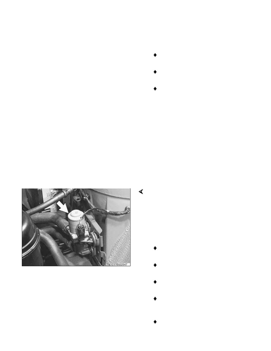
The E46 uses a single water valve and
heater core to provide passenger
compartment heat. The water valve is
electrically pulsed to control the flow of
coolant through the heater core.

Temperature regulation is based on the
following inputs:

Temperature control switch setting

Interior temperature sensor signal

Ambient temperature signal

Heater core temperature sensor
signal

Evaporator temperature signal

Solar sensor input (if applicable)

A rocker switch is used to select the
desired cabin temperature, shown in the
display matrix of the control panel. The
range for temperature display is from 15°
to 32°C (60° to 90°F).

A "service station" feature is integrated
into the E46 IHKA. This prevents the
heater core from being flooded with hot
coolant when refueling the vehicle.


Blower control

The blower rocker switch on the IHKA
control panel is the master switch for the
entire system. Rocking the switch to
select slower and slower fan speeds
eventually results in the following:

Blower motor turns off.

All air distribution valves are closed.

LED and LCD displays are switched
off.

Rear window defroster is switched
off.

A/C compressor is switched off.

Even in the lowest setting, the interior
temperature sensor blower continues to
operate and the IHKA control panel
continues to signal the heater water
valve for heat.


Regulated A/C compressor

The operation of the A/C compressor is
modulated, eliminating noticeable on/off
cycling. In order to reduce fuel
consumption and improve vehicle
performance, the system default is with
the compressor OFF.

The A/C system uses a variable
displacement compressor. The swash
plate of the compressor is hinged so that
is can vary piston travel based on output
requirements of the system.

A/C compressor function is controlled by
the Engine Control Module (ECM) based
on inputs from the IHKA control panel.
Pressing the "snowflake" button is a
request for A/C activation. As long as the
evaporator temperature is above 2°C
(36°F), the IHKA signals the ECM to
activate the compressor.

The IHKA control module sends the
following signals to the ECM over the
K-bus and CAN-bus via the instrument
cluster:

Request for A/C activation

Load torque for switching the
compressor

Requested cooling fan speed

The IHKA determines the load torque for
compressor activation and required
engine cooling fan speed from the
pressure sensor mounted on the
receiver/dryer. The pressure sensor
provides a linear voltage input signal (0 -
5 volts) to the IHKA control module. The
module processes this signal and
determines the load torque of the system
(0 to 30 Nm with a variable displacement
compressor). The higher the pressure in
the system, the higher the voltage input
signal to the IHKA module. The output

signal to the ECM enables the ECM to
modify the idle speed, timing and fuel
injection amount based on the load that
is imposed when the compressor is
activated.


Regulated engine cooling fan
operation

The engine cooling fan (arrow) operates
at variable speeds (15 stages) based on
cooling system load. The ECM activates
the fan through a pulse modulated final
stage control. See 

170 Radiator and

Cooling System

 for further details.

Note:

Automatic transmission models: The
engine cooling fan is located in front
of the radiator. A belt-driven fan and
fan clutch assembly is installed at
the rear of the radiator.

Standard transmission models: The
electric engine cooling fan is
installed at the rear of the radiator.


A/C system


Content   ..  278  279  280  281   ..