Acura RSX Honda Integra. Manual - part 430


  Index      Acura     Acura RSX Honda Integra - service repair manual 2002-2006 year


Search            


Content   ..  428  429  430  431   ..


Acura RSX Honda Integra. Manual - part 430


*01

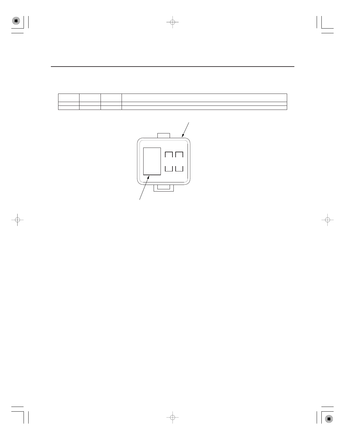
Auxiliary Under-dash Fuse/Relay Box (’05-06 models)

Fuse

Number

Amps

Wire Color

Component(s) or Circuit(s) Protected

22-58

Power Distribution

Fuse to Components Index (cont’d)

IGNITION COIL RELAY

31

32

AUXILIARY UNDER-DASH
FUSE/RELAY BOX

31

15 A

BLU

Ignition coil relay

32

15 A

WHT/BLK

PGM-FI main relay

05/06/27 18:02:55 61S6M040_220_0059

S6M6A00J54230100000CCAT00

Ground

Component(s) or circuit(s) grounded

22-59

Ground Distribution

Ground to Components Index

G1

Battery, Transmission housing

G2

Engine mount bracket

G101

ECM/PCM (PG1 and PG2 are BLK; LG1 and LG2 are BRN/YEL),
CMP sensor, CKP sensor, Data link connector (DLC), Immobilizer control unit-receiver, Idle air control (IAC) valve, Ignition coils,
Input shaft (mainshaft) speed sensor (A/T) , Output shaft (countershaft) speed sensor (A/T) , TDC sensor, Transmission
range switch (A/T), Vehicle speed sensor (VSS) (M/T) , Rocker arm oil pressure switch (VTEC oil pressure switch), Rocker arm
oil control solenoid (VTEC solenoid valve)
Shielding between the ECM/PCM and Knock sensor has BRN/YEL wire

G201

Right headlight (low beam), Right front parking light, Right front turn signal light, Right front side marker light

G202

ABS modulator-control unit (2 wires)

G301

Blower motor relay, ELD unit, Left headlight (low beam), Left front parking light, Left front turn signal light, Windshield and
rear window washer motors, Windshield washer fluid level switch (Canada), Power window relay, Turn signal/hazard relay,
Multiplex control unit (3 wires), Multiplex control unit service check connector, Left front side marker light

G302

A/C condenser fan motor, Hood switch (security), Radiator fan motor, Radiator fan switch

G401

Combination light switch, Cruise control unit, Cruise control main switch, Data link connector (DLC), Daytime running lights
control unit (Canada) (2 wires), Driver’s door lock knob switch, Driver’s door lock switch, Driver’s door key cylinder switch,
Front accessory power socket, Gauge assembly, Ignition key switch, Keyless receiver unit, Left power mirror defogger
(Canada), Moonroof open/close relays, Moonroof switch, Multiplex control unit (2 wires), Power mirror switch, Power window
master switch (2 wires), Rear accessory power socket relay (USA), Security control unit , Wiper/washer switch (windshield
and rear window)

G402

Climate control unit, Clutch pedal position switch (M/T), Clutch interlock switch (M/T), Gauge assembly, Glove box light,
Ignition key switch (A/T), Park pin switch/shift lock solenoid (A/T), Power transistor, Seat heater relay (Canada), Seat heater
switch (Canada), Shift lock relay (A/T), Passenger’s door lock switch, Passenger’s door lock knob switch, Passenger’s door key
cylinder switch, Right power mirror defogger (Canada), Security control unit

G403

Audio unit
Shielding between the audio unit and speaker has RED/BLU wire (With BOSE sound system)

G404

SRS unit (2 wires), SRS front sensors

G451

Brake fluid level switch, Cruise control actuator, Power steering pressure (PSP) switch, Windshield wiper motor

G501

Fuel gauge sending unit, Fuel pump, Memory erase signal (MES) connector, Optional rear accessory power socket (Canada),
Rear accessory power socket (USA), Seat belt switches, Seat heaters (Canada), OPDS unit

G502

Front BOSE stereo amplifier, Rear BOSE stereo amplifier, Rear BOSE stereo amplifier relay

G601

Left taillight/brake lights (2 wires), Left back-up light, Left rear side marker light, Left rear turn signal light, License plate light,
Right taillight/brake lights (2 wires), Right back-up light, Right rear side marker light, Right rear turn signal light, Trailer lighting
connector

G701

Hatch latch switch, High mount brake light, Rear window wiper motor, Security hatch lock knob switch, Shielding (High mount
brake light, Hatch latch switch), Shielding (High mount brake light, Hatch latch switch)

G702

Shielding (Rear window wiper motor, Condenser, Hatch lock actuator)

1: ’02-04 models
2: ’05-06 models

1

1

1

2

2

1

2

2

1

05/06/27 18:02:55 61S6M040_220_0060

01

S6M6A00J54226562001KDAT00

Removal

Installation

22-60

Under-dash Fuse/Relay Box

Removal and Installation

A

B

SRS components are located in this area. Review the
SRS component locations (see page 23-10) and
precautions and procedures (see page 23-11) before
performing repairs or service.

1. Make sure you have the anti-theft code for the radio,

then write down the frequencies for the radio’s
preset buttons.

2. Disconnect the battery negative cable, then

disconnect the positive cable, and wait at least
3 minutes.

3. Remove the dashboard lower cover (see page

20-63).

4. Disconnect the connectors from the fuse side of the

under-dash fuse/relay box.

5. Remove the mounting bolt and slide the under-

dash fuse/relay box (A) down from the bracket (B).

6. Disconnect the connectors from the back of the

under-dash fuse/relay box, and remove the fuse/
relay box.

NOTE: The SRS connector is a spring-loaded lock
type (see page 23-15).

1. Install the under-dash fuse/relay box in the reverse

order of removal and connect all connectors to the
under-dash fuse/relay box.

2. Install the dashboard lower cover.

3. Connect both the negative cable and positive cable

to the battery.

4. Enter the anti-theft code for the radio, then enter

the customer’s radio station presets.

5. Reset the power window control unit (see page

22-148).

6. Confirm that all systems work properly.

05/06/27 18:03:16 61S6M040_220_0061

S6M6A00J54200014401FEAT00

22-61

Battery

Battery Test

A battery can explode if you do not follow the
proper procedure, causing serious injury to anyone
nearby. Follow all procedures carefully and keep
sparks and open flames away from the battery.

Use either a JCI or Bear ARBST tester, and follow the
manufacturer’s procedures. If you don’t have one of
these computerized testers, follow this conventional
test procedure:

1. Be sure the temperature of the electrolyte is

between 70 °F (21 °C) and 100 °F (38 °C).

2. Inspect the battery case for cracks or leaks.

• If the case is damaged, replace the battery.
• If the case looks OK, go to step 3.

3. Check the indicator EYE.

• If the EYE indicates the battery is charged, go to

step 4.

• If the EYE indicates a low charge, go to step 7.

4. Apply a 300 A load for 15 seconds to remove the

surface charge.

5. Wait 15 seconds, then apply a test load of 280 A for

15 seconds.

6. Record battery voltage.

• If voltage is above 9.6 V, the battery is OK.
• If voltage is below 9.6 V, go to step 7.

7. Charge the battery on High (40 A) until the EYE

shows the battery is charged, plus an additional
30 minutes. If the battery charge is very low, it may
be necessary to bypass the charger’s polarity
protection circuitry.

• If the EYE indicates the battery is charged within

3 hours, the battery is OK.

• If the EYE indicates the battery is not charged

within 3 hours, replace the battery.

05/06/27 18:03:16 61S6M040_220_0062


Content   ..  428  429  430  431   ..