Acura RSX Honda Integra. Manual - part 156


  Index      Acura     Acura RSX Honda Integra - service repair manual 2002-2006 year


Search            


Content   ..  154  155  156  157   ..


Acura RSX Honda Integra. Manual - part 156


±

01

S6M6AACK72100090507FAAT00

DTC P0507:

YES

NO

YES

NO

11-330

Idle Control System

DTC Troubleshooting (cont’d)

A

Idle Control System RPM Higher

Than Expected
(2004 model)

NOTE:

• If DTC P0511 is stored at the same time as DTC P0507,

troubleshoot DTC P0511 first; then recheck for DTC
P0507.

• Information marked with

1 applies to K20A3

engine;

2 applies to K20A2 engine.

1. Start the engine. Hold the engine speed at

3,000 rpm without load (in Park or neutral) until the
radiator fan comes on, then let it idle.

2. Check the engine speed at idle without load

conditions: headlights, blower fan, rear defogger,
and air conditioner off.

Intermittent failure, system is OK at this

time.

Go to step 3.

3. Turn the ignition switch OFF.

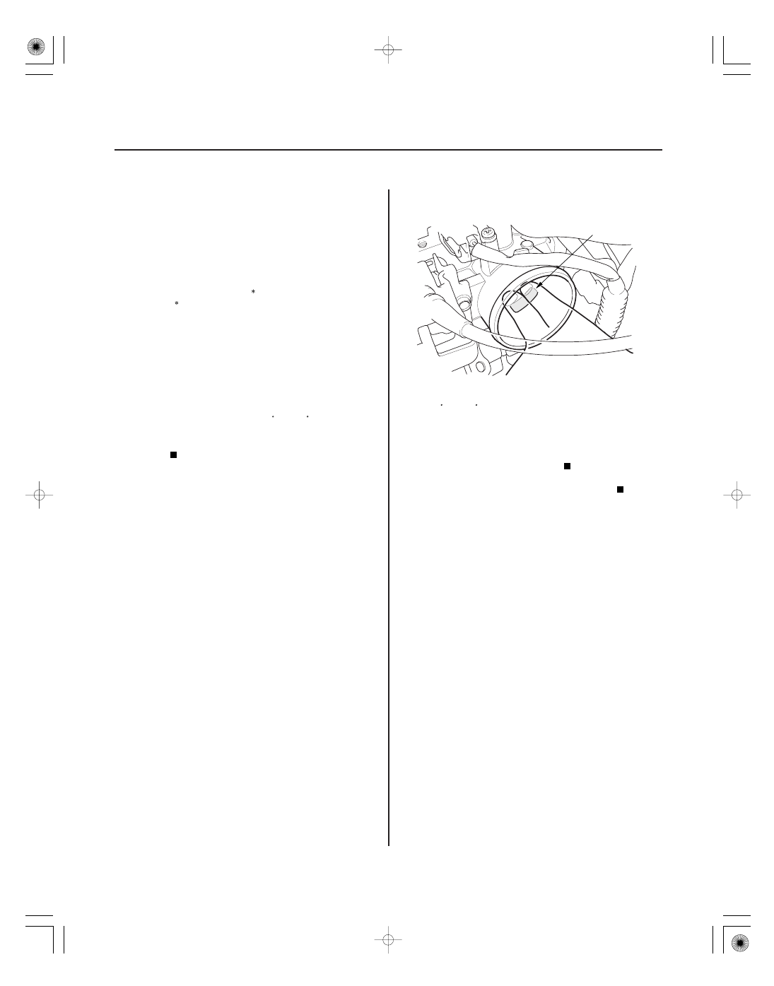
4. Remove the air cleaner from the throttle body

(see page 11-407).

5. Start the engine, and let it idle.

6. Put your fingers on the lower port (A) in the throttle

body.

Check the idle speed with a different load

condition (electrical, A/C, gear position, P/S etc.)
(see page 11-348). If it’s out of specification, replace
the IAC valve (see page 11-412).

Check for vacuum leaks at these parts.

• PCV valve
• PCV hose
• EVAP canister purge valve
• Throttle body
• Intake manifold
• Brake booster hose
• Intake air bypass control thermal valve

Is the engine r unning at 650

( 7 00)

50 r pm?

Does the engine speed dr op below
7 00

( 7 50)

r pm?

1

2

1

2

05/06/27 17:40:24 61S6M040_110_0330

S6M6AALK72100090507FAAT00

DTC P0507:

YES

NO

YES

NO

YES

NO

YES

NO

11-331

Idle Control System RPM Higher

Than Expected
(2005-2006 models)

1. Turn the ignition switch ON (II).

2. Clear the DTC with the HDS.

3. Start the engine, Hold the engine speed at

3,000 rpm without load (in Park or neutral) until the
radiator fan comes on, then let it idle.

4. Monitor the OBD STATUS for DTC P0506 in the

DTCs MENU with the HDS.

Go to step 5.

If the screen indicates PASSED, intermittent

failure, system is OK at this time. If the screen
indicates EXECUTING, let the engine idle until a
result comes on. If the screen indicates OUT OF
CONDITION, recheck with different load conditions
(electrical, A/C, gear position, etc.), then go to
step 3.

5. Check for vacuum leaks at these parts:

• PCV valve
• PCV hose
• EVAP canister purge valve
• Throttle body
• Intake manifold
• Brake booster hose
• Intake air bypass control thermal valve

Repair or replace the leaking part(s), then go

to step 6.

Go to step 6.

6. Turn the ignition switch ON (II).

7. Reset the ECM/PCM with the HDS.

8. Do the ECM/PCM idle learn procedure (see page

11-349).

9. Start the engine. Hold the engine speed at

3,000 rpm without load (in Park or neutral) until the
radiator fan comes on, then let it idle.

10. Check for Temporary DTCs or DTCs with the HDS.

If DTC P0507 is indicated, check for poor

connections or loose terminals at the throttle body,
and the ECM/PCM, then go to step 1. If any other
Temporary DTCs or DTCs are indicated, go to the
indicated DTC’s troubleshooting.

Go to step 11.

11. Monitor the OBD STATUS for DTC P0507 in the

DTCs MENU with the HDS.

Troubleshooting is complete.

If the screen indicates FAILED, check for poor

connections or loose terminals at the throttle body,
and the ECM/PCM, then go to step 1. If the screen
indicates EXECUTING, let the engine idle until a
result comes on. If the screen indicates OUT OF
CONDITION, recheck with different load conditions
(electrical, A/C, gear position, etc.), then go to
step 9.

Does the scr een indicate F AILED ?

Ar e ther e any leaks?

Ar e any T empor ar y DT Cs or DT Cs indicated?

Does the scr een indicate PASSED?

05/06/27 17:40:54 61S6M040_110_0331

01

02

01

S6M6AACK72100090511FAAT00

DTC P0511:

DTC P1519:

YES

NO

YES

NO

YES

NO

YES

NO

11-332

Idle Control System

DTC Troubleshooting (cont’d)

IAC VALVE 3P CONNECTOR

IGP (YEL/BLK)

IAC VALVE 3P CONNECTOR

PG1 (BLK)

ECM/PCM CONNECTOR A (31P)

IACV (BLK/RED)

IAC Valve Circuit Malfunction

(2004 model)

IAC Valve Circuit Malfunction

(2002-2003 models)

NOTE:

• Information marked with an asterisk ( ) applies to

2004 model.

• Information marked with double asterisk (

) applies

to 2002-2003 models.

1. Reset the ECM/PCM (see page 11-4).

2. Turn the ignition switch ON (II).

Go to step 3.

Intermittent failure, system is OK at this time.

Check for poor connections or loose terminals the
IAC valve and the ECM/PCM.

3. Turn the ignition switch OFF.

4. Disconnect the IAC valve 3P connector.

5. Turn the ignition switch ON (II).

6. Measure voltage between IAC valve 3P connector

terminal No. 2 and body ground.

Go to step 7.

Repair open in the wire between the IAC valve

and the PGM-FI main relay.

7. Turn the ignition switch OFF.

8. Check for continuity between body ground and IAC

valve 3P connector terminal No. 1.

Go to step 9.

Repair open in the wire between the IAC valve

and G101.

9. Disconnect ECM/PCM connector A (31P).

10. Check for continuity between body ground and

ECM/PCM connector terminal A12.

Repair short in the wire between the IAC

valve and the ECM/PCM (A12).

Go to step 11.

Wire side of female terminals

Wire side of female terminals

Wire side of female terminals

Is DT C P0511 ( P1519)

indicated?

Is ther e batter y voltage?

Is ther e continuity?

Is ther e continuity?

05/06/27 17:40:55 61S6M040_110_0332

03

02

03

YES

NO

YES

NO

11-333

IAC VALVE 3P CONNECTOR

JUMPER WIRE

IACV (BLK/RED)

ECM/PCM CONNECTOR A (31P)

IACV (BLK/RED)

ECM/PCM CONNECTOR A (31P)

IACV (BLK/RED)

11. Connect IAC valve 3P connector terminal No. 3 and

body ground with a jumper wire.

12. Check for continuity between ECM/PCM connector

terminal A12 and body ground.

Go to step 13.

Repair open in the wire between the IAC valve

and the ECM/PCM (A12).

13. Reconnect the IAC valve 3P connector.

14. Turn the ignition switch ON (II).

15. Measure voltage between body ground and ECM/

PCM connector terminal A12.

Update the ECM/PCM if it does not have the

latest software, or substitute a known-good ECM/
PCM (see page 11-6), then recheck. If the symptom/
indication goes away with a known-good ECM/PCM,
replace the original ECM/PCM (see page 11-284).

Replace the IAC valve (see page 11-412).

Wire side of female terminals

Wire side of female terminals

Wire side of female terminals

Is ther e continuity?

Is ther e batter y voltage?

05/06/27 17:40:55 61S6M040_110_0333


Content   ..  154  155  156  157   ..