Acura RSX Honda Integra. Manual - part 33


  Index      Acura     Acura RSX Honda Integra - service repair manual 2002-2006 year


Search            


Content   ..  31  32  33  34   ..


Acura RSX Honda Integra. Manual - part 33


01

*01

S6M6A20A14500017621FHAT02

01

02

S6M6A20A14500017601FEAT00

4-68

4-68

Cruise Control

Cruise Control Set/decel, Resume/
accel, Cancel Switch Test/
Replacement

Cruise Control Actuator Test

Terminal

Position

Set/decel (PRESSED)

Resume/accel (PRESSED)

Cancel (PRESSED)

3

2

1

B

A

A

B

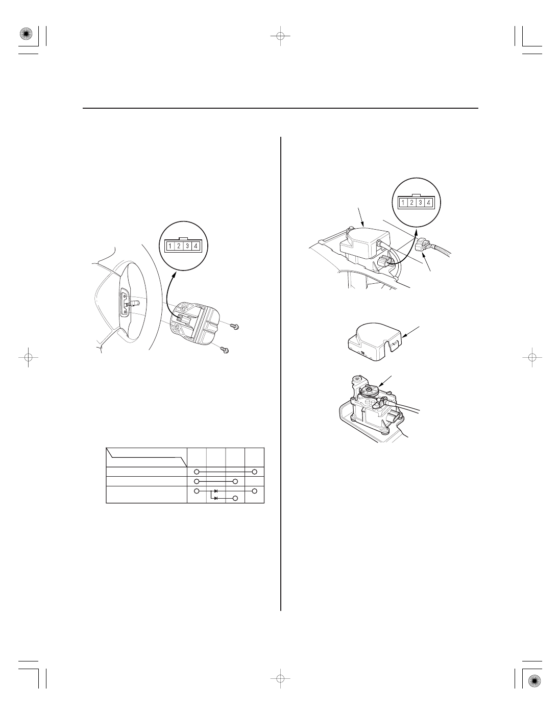
SRS components are located in this area. Review the
SRS component locations (see page 23-10), and the
precautions, and procedures (see page 23-11), before
performing repairs or service.

1. Remove the two screws, then remove the switch.

2. Check for continuity between the terminals in

switch position according to the table.

• If there is continuity, and it matches the table, but

switch failure occurred on the cruise control unit
input test, check and repair the wire harness on
the switch circuit.

• If there is no continuity in one or both positions,

replace the switch.

1. Disconnect the 4P connector (A) from the cruise

control actuator (B).

2. Remove the cover (A), and check the output linkage

(B) for smooth movement.

3. Connect the battery power to the No. 2 terminal

and ground to the No. 1 terminal.

4. Check for a clicking sound from the magnetic clutch.

The output linkage should be locked.

5. If the output linkage is not locked, replace the

cruise control actuator assembly.

Terminal side of
male terminals

Terminal side of
male terminals

01

01

02

S6M6A20A14500017601KBAT10

4-69

4-69

Cruise Control Actuator/Cable
Replacement

FULL OPEN

MIDDLE
POSITION

FULL CLOSE

OUTPUT LINKAGE

6 x 1.0 mm
12 N·m
(1.2 kgf·m, 8.7 lbf·ft)

A

B

C

B

A

6. Check the operation of the actuator motor in each

output linkage position according to the table. You
should be able to hear the motor.

Output linkage position

(

)

(

)

1. K20A3 engine: Remove the throttle cover (A), fully

open the cruise control link by hand, then remove
the cruise control cable (B) from link. Loosen the
locknut (C), and remove the cable from the bracket.

2. K20A2, K20Z1 engines: Fully open the cruise

control link by hand, then remove the cruise control
cable (A) from the link. Loosen the locknut (B), and
remove the cable from the bracket.

(cont’d)

Battery power

polarities

No. 4
Terminal

No. 3
Terminal

The
motor
runs.

The
motor
runs.

The
motor
stops.

No. 3
Terminal

No. 4
Terminal

The
motor
stops.

The
motor
runs.

The
motor
runs.

FULL
CLOSE

MIDDLE
POSITION

FULL
OPEN

03

04

05

4-70

Cruise Control

Cruise Control Actuator/Cable Replacement (cont’d)

6 x 1.0 mm
12 N·m
(1.2 kgf·m,
8.7 lbf·ft)

A

B

3. Remove the cowl cover (see page 20-105).

4. Disconnect the 4P connector, and remove the two

bolts securing the cruise control actuator.

5. Remove the actuator cover (A), then remove the

actuator cable (B) from the cruise control actuator.

6. Remove the bracket from the cruise control

actuator.

7. Install in the reverse order of removal, and adjust

the free play at the throttle linkage after connecting
the actuator cable.

±

±

01

S6M6A20A14500017602MBAT00

01

02

S6M6A0AA14500017045FEAT00

4-71

4-71

Cruise Control Actuator Cable
Adjustment

Clutch Pedal Position Switch Test

D

C

B

A

CLUTCH PEDAL POSITION SWITCH 2P CONNECTOR

A

Terminal

Clutch Pedal
Position Switch

PRESSED

1

2

RELEASED

1. Check that the actuator cable (A) moves smoothly

with no binding or sticking.

2. Measure the amount of movement of the output

linkage (B) until the engine speed starts to increase.
At first, the output linkage should be located at the
fully closed position (C). The free play (D) should be
3.75

0.5 mm (0.15

0.02 in.).

3. If the free play is not within specifications, loosen

the locknut, and turn the adjusting nut until the free
play is as specified, then retighten the locknut.

1. Disconnect the 2P connector from the clutch pedal

position switch (A).

2. Remove the clutch pedal position switch.

3. Check for continuity between the terminals

according to the table.

• If the continuity is not as specified, replace the

clutch pedal position switch.

• If OK, install the clutch pedal position switch, and

adjust the pedal height (see page 12-6).

Terminal side of
male terminals


Content   ..  31  32  33  34   ..