Acura RSX Honda Integra. Manual - part 23


  Index      Acura     Acura RSX Honda Integra - service repair manual 2002-2006 year


Search            


Content   ..  21  22  23  24   ..


Acura RSX Honda Integra. Manual - part 23


01

02

03

S6M6A00A26100055901MAAT00

Electrode Gap
Standard (New):

1.0

1.1 mm

(0.039

0.043 in.)

Service Limit:

1.3 mm (0.051 in.)

Spark Plugs
K20A3 Engine: IZFR6K11 (NGK)

SKJ20DR-M11 (DENSO)

K20A2 Engine: IFR7G11K (NGK)

IFR7G11KS (NGK)
SK22PR-M11 (DENSO)
SK22PR-M11S (DENSO)

K20Z1 Engine: IFR7G11KS (NGK)

SK22PR-M11S (DENSO)

Specified Torque
IFR7G11KS (NGK), SK22PR-M11S (DENSO):
25 N·m (2.5 kgf·m, 18 lbf·ft)
Except IFR7G11KS (NGK), SK22PR-M11S (DENSO):
18 N·m (1.8 kgf·m, 13 lbf·ft)

4-28

Ignition System

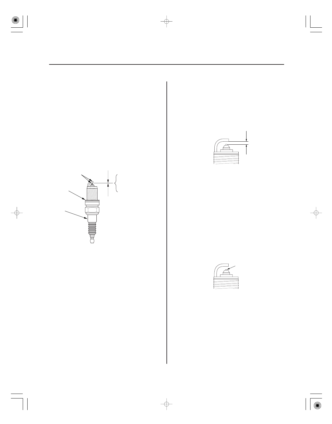
Spark Plug Inspection

• Improper gap
• Oil-fouling
• Carbon deposits
• Cracked center

electrode insulator

Worn or deformed
electrodes

Damaged
gasket

Cracked
insulator

A

A

1. Inspect the electrodes and ceramic insulator.

• Burned or worn electrodes may be caused by:

– Advanced ignition timing
– Loose spark plug
– Plug heat range too hot
– Insufficient cooling

• Fouled plug may be caused by:

– Retarded ignition timing
– Oil in combustion chamber
– Incorrect spark plug gap
– Plug heat range too cold
– Excessive idling/low speed running
– Clogged air cleaner element
– Deteriorated ignition coils

2. If the spark plug electrode is dirty or contaminated,

clean the electrode with a plug cleaner.

NOTE:

• Do not use a wire brush or scrape the iridium

electrode since this will damage the electrode.

• Use a chemical cleaner such as Carb Spray to

clean contamination on the electrode.

• When using a sand blaster spark plug cleaner, do

not clean for more than 20 seconds to avoid
damaging the electrode.

3. Do not adjust the gap of iridium tip plugs (A);

replace the spark plug if the gap is out of
specification.

4. Replace the plug at the specified interval, or if the

center electrode is rounded (A). Use only the spark
plugs listed.

5. Apply a small amount of anti-seize compound to

the plug threads, and screw the plugs into the
cylinder head, finger-tight. Then torque them.

*01

S6M6A00A14100000000DAAT00

4-29

Charging System

Component Location Index

CHARGING SYSTEM INDICATOR
(In the gauge assembly)

UNDER-HOOD FUSE/RELAY BOX
(Has built-in ELECTRICAL LOAD
DETECTOR (ELD) UNIT)

BATTERY

ALTERNATOR

DRIVE BELT

AUTO-TENSIONER

Test, page 22-61

Troubleshooting, page 4-32
Removal and Installation,

page 4-46

Overhaul

K20A3 engine, page 4-48
K20A2, K20Z1 engines, page 4-53

Inspection, page 4-43
Replacement, page 4-43

Inspection, page 4-44
Replacement, page 4-45

S6M6A00A14100000000HBAT00

2002-2004 Models

Symptom

Diagnostic procedure

Also check for

2005-2006 Models

Symptom

Diagnostic procedure

Also check for

4-30

Charging System

Symptom Troubleshooting Index


Charging system
indicator does not come
on with the ignition
switch ON (II)

Troubleshoot the charging system indicator circuit:

K20A3 engine (see page 4-32).
K20A2 engine (see page 4-35).

Charging system
indicator stays on

1.

2.
3.

Troubleshoot the charging system indicator circuit:

K20A3 engine (see page 4-32).
K20A2 engine (see page 4-35).

Check for a broken drive belt (see page 4-43).
Check the drive belt auto-tensioner (see page 4-44).

Battery discharged

1.

2.
3.
4.
5.

6.
7.

Check for a poor connection, and for open or shorted
wire(s) in charging system.
Check for parastic electrical current draw.
Check for a broken drive belt (see page 4-43).
Check the drive belt auto-tensioner (see page 4-44).
Troubleshoot the alternator and regulator circuit
(see page 4-39).
Check for a poor connection at the battery terminal.
Test the battery (see page 22-61).

Battery overcharged

1.

2.

Troubleshoot the alternator and regulator circuit
(see page 4-39).
Test the battery (see page 22-61).


Charging system
indicator does not come
on with the ignition
switch ON (II)

Troubleshoot the charging system indicator circuit:

K20A3 engine (see page 4-33).
K20Z1 engine (see page 4-37).

Charging system
indicator stays on

1.
2.

3.
4.

Check for PGM-FI DTCs (see page 11-3).
Troubleshoot the charging system indicator circuit:

K20A3 engine (see page 4-33).
K20Z1 engine (see page 4-37).

Check for a broken drive belt (see page 4-43).
Check the drive belt auto-tensioner (see page 4-44).

Battery discharged

1.
2.
3.
4.

5.
6.

Check for parastic electrical current draw.
Check for a broken drive belt (see page 4-43).
Check the drive belt auto-tensioner (see page 4-44).
Troubleshoot the alternator and regulator circuit
(see page 4-39).
Check for a poor connection at the battery terminal.
Test the battery (see page 22-61).

Battery overcharged

1.

2.

Troubleshoot the alternator and regulator circuit
(see page 4-39).
Test the battery (see page 22-61).

*01

S6M6A00A14100000000EAAT00

4-31

Circuit Diagram

IG1 HOT in ON (II)
and START (III)

No. 20*1

ALTERNATOR

RECTIFIER

FR

BATTERY

ELD UNIT

BLK/YEL

VOLTAGE REGULATOR

L

IG

C

B

FIELD WINDING

BLK

G301

UNDER-HOOD FUSE/RELAY BOX

WHT

No. 19 (100 A)

GRN/RED

IG1

BAT

WHT/BLU

BLK/YEL

BLK/ORN

ATLC

IGNITION SWITCH

ALTL

ALTF

5 V

12 V

MULTIPLEX
CONTROL
UNIT

No. 10 (7.5 A)

UNDER-DASH
FUSE/RELAY BOX

ECM/PCM

BLK/ORN

WHT

YEL

WHT/GRN

CPU

DRIVER

CHARGING
SYSTEM
INDICATOR

GAUGE ASSEMBLY

YEL

ELD

SEFMJ

WHT/RED

WHT/GRN

No. 4
(10 A)

*3

*2

*1 No. 20 (40 A): USA model

No. 20 (50 A): Canada model

*2 2002-2004 models
*3 2005-2006 models

*2

*3


Content   ..  21  22  23  24   ..