Acura RL (1996-2004 year). Manual - part 633


  Index      Acura     Acura RL 1996-2004 year - service repair manual


Search            


Content   ..  631  632  633  634   ..


Acura RL (1996-2004 year). Manual - part 633


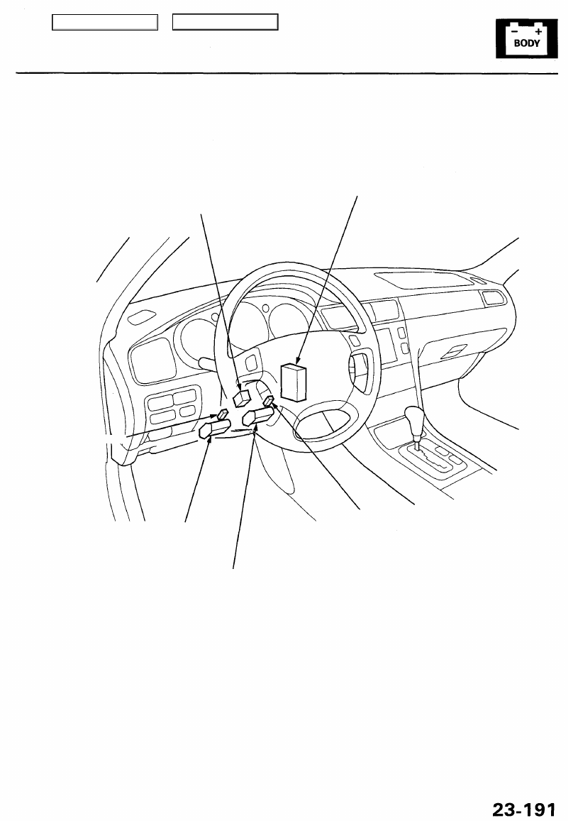
EXTEND-RETRACT MOTOR

Test, page 

23-226

TILT MOTOR
Test, page 

23-226

EXTEND-RETRACT SENSOR
Test, page 

23-226

TILT POSITION SENSOR
Test, page 

23-226

STEERING COLUMN
SWITCH

Test, page 

23-225

STEERING COLUMN CONTROL
UNIT
Input Test, page 

23-230

Main Menu

Table of Contents

Driving Position Memory System (DPMS)

Description

The driver's seat, the power mirrors and the steering column, whose positions are determined the driver's position, have
a memory feature. The seat adjustments, the mirror adjustments, and the steering column adjustments can be regulated

separately. All of adjustments can be memorized by the pressing the MEMO button on the driving position memory
switch, and then pressing one of the two position buttons within 5 seconds. Pressing the appropriate position button will

move the seat, the mirror and the steering column to the position memorized for driver 1 or driver 2, eliminating manual
adjustments when changing drivers.

NOTE: Disconnecting the battery will cancel the memorized positions.

STEERING COLUMN POSITION SENSORS

By means of the variable resistor-type tilt position sensor and extend-retract position sensor, the steering column control
unit detects the voltage changes caused by the movements of the steering column. These voltage changes are stored in
memory, and the steering column position is memorized.

POWER SEAT POSITION SENSORS
Each motor has a reed switch sensor which detects motor rotation and sends a pulse to the power seat control unit when
the motor rotates. The control unit stores the number of pulses in its memory, and the seat position is memorized.

POWER MIRROR POSITION SENSORS
By means of a Hall-effect type tilt position sensor and swing position sensor, the power mirror control unit detects the

voltage changes caused by the movements of the mirrors.
These voltage changes are stored in memory, and the power mirror positions are memorized.

"AUTO" SWITCH FUNCTION

When the ignition key is pulled out (ignition switch turned OFF) with the AUTO switch in the steering column switch ON

and the vehicle parked (shift lever in the steering column will automatically move to the highest tilt position and fully
retracted position to ease exit from the vehicle.

When the ignition key is inserted into the ignition key switch with the AUTO switch ON and the vehicle parked (shift lever

in the steering column will automatically move back to the previous position.

MEMORY RETRIEVE
When one of the two buttons on the driving position memory switch is pressed with the vehicle parked (shift lever in
the seat, the mirror, and the steering column move to the memorized positions.

Main Menu

Table of Contents

MEMORY RANGES
Seat and steering column positions can be memorized within these ranges:
NOTE: The power mirror position can be memorized within all ranges of the mirror movements.

Power Seat:

NEUTRAL

Steering Column:

240 mm

(9.4 in)

40 mm

(1.6 in)

RETRACT

EXTEND

TILT DOWN

TILT UP

30 mm (1.2 in)

Main Menu

Table of Contents

Driving Position Memory System (DPMS)

Self-diagnostic Procedures

The self-diagnostic function of the driving position memory system detects system problems, and stores up to 5 problem
causes in memory. This information can be retrieved by displaying the diagnostic trouble code.

Displaying the Diagnostic Trouble Code (DTC)

1. Turn the ignition switch OFF.

2. Press the MEMO button and both position buttons

at the same time, and hold them.

3. Turn the ignition switch ON (II), and wait at least

1 second, then release the three buttons.

4. After 1 second, the position button indicators will

blink to show the DTC.

DTC Indications
No System Problem:

If there is no DTC stored, the indicators blink only once (3 seconds).

INDICATORS (LED)

Indicator 1

indicator 2

Ignition

switch

MEMO button
Pos. button 1
Pos. button 2

System Problem(s) Exist(s) (Example shows DTC 12):

Up to five DTCs can be indicated in the order the problems occurred. The first digit is indicated by the number of long
(1 second) blinks, and the second digit is indicated by the number of short (0.26 second) blinks. There is a 3 second break
between each DTC when there are multiple DTCs.

MEMO button

Pos. button 1

Pos. button 2

Ignition switch

Indicator 1

Indicator 2

Cancelling the DTC Indication

• Turn the ignition switch OFF or
• Press the MEMO button, or the position button 1, or the position button 2, or
• Press one of the driving position adjustment switches.

Erasing the DTC from Memory
NOTE:
• The PCM memory setting is needed after reconnecting the battery (see 

section 11

).

• Make sure you have the anti-theft code for the radio, then write down the frequencies for the radio's preset button, and

after reconnecting the battery enter the anti-theft code for the radio, then enter the customer's radio station presets.

Disconnect the battery negative cable for at least 30 seconds.

Main Menu

Table of Contents


Content   ..  631  632  633  634   ..