Acura RL (1996-2004 year). Manual - part 288


  Index      Acura     Acura RL 1996-2004 year - service repair manual


Search            


Content   ..  286  287  288  289   ..


Acura RL (1996-2004 year). Manual - part 288


OnStar System

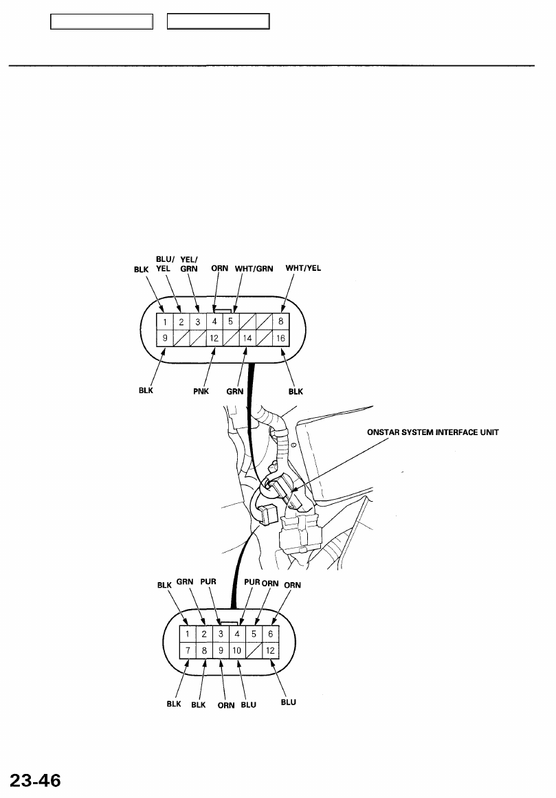
OnStar System Interface Unit Input Test

'03 Model

1. Remove the rear seat (Refer to the '96 - '01 3.5RL Service Manual, P/N 61SZ305, for the items not shown in this sec-

tion).

2. Disconnect the 12P connector from the OnStar system interface unit.
3. Inspect the connector and socket terminals to be sure they are all making good contact.

• If the terminals are bent, loose or corroded, repair them as necessary, and recheck the system.
• If the terminals look OK, make the following input tests at the connector.

— If any test indicates a problem, find and correct the cause, then recheck the system.
— If all the input tests prove OK, the control unit must be faulty; replace it.

Main Menu

Table of Contents

Disconnect the connectors from the unit

Cavity Wire Test condition

Test: Desired result

Possible cause if result is not obtained

A1

A7

BLK

Under all conditions

Check for continuity to ground:

There should be continuity.

• An open in the wire

Reconnect the connectors from the unit

Cavity Wire Test condition

Test: Desired result

Possible cause if result is not obtained

B2

B3

B4

B5

A12

A3

A9

A6

A10

A8

A5

A2

A4

B12

B14

BLU/YEL

YEL/GRN

ORN

WHT/GRN

BLU

PUR

ORN

ORN

BLU

BLK

ORN

GRN

PUR

PNK

GRN

Ignition switch in ACC (I)

Ignition switch in ACC (I)

With the ignition switch

OFF, press and hold the

"DOT" button. Turn the
ignition switch from OFF

to ACC three times and

back to ACC, then release

the "DOT" button.

Ignition switch in ACC (I)

Ignition switch in ACC (I)

Ignition switch turned
OFF

With the ignition switch

OFF, press and hold the

"DOT" button. Turn the
ignition switch from OFF

to ACC three times and

back to ACC, then release

the "DOT" button.

Ignition switch in ACC (I)

Under all conditions

Ignition switch in ACC (I)

Ignition switch in ACC (I)
OnStar "DOT" button

pushed

Ignition switch in ACC (I)

Ignition switch in ACC (I)

Ignition switch in ACC (I)

Ignition switch in ACC (I) On-
Star "DOT" button pushed

Ignition switch in ACC (I)

Check for voltage to ground:

There should be approx 8V.

Check for voltage to ground:

"DOT" button pushed: 280mV
"OnStar" button pushed: 1V
"Emergency" button pushed: 1.7V

Check for voltage to ground:
There should be 4V.

Check for voltage to ground:

There should be about 8V.

Check for voltage to ground:

There should be no voltage.

Check for voltage to ground:

There should be 10V.

Check for voltage to ground:
There should be 4V.

Check for voltage to ground:

There should be less than 1V.

Check for continuity to ground:
There should be continuity.

Check for voltage to ground:
There should be about 8V.

Check for voltage to ground:

There should be about 8V.

Check for voltage to ground:
There should be about 8V.

Check for voltage to ground:
There should be about 8V.

Check for voltage to ground:

"DOT" button pushed: 280mV
"OnStar" button pushed: 1V
"Emergency" button pushed: 1.7V

Check for voltage to ground:
There should be about 8V.

Check for voltage to ground:
There should be about 4V.

• Blown No. 56 (7.5 A) fuse in the

under-hood fuse/relay box

• An open in the wire

• Faulty OnStar button
• An open in the wire

• Faulty OnStar button
• An open in the wire

• Faulty OnStar button
• An open in the wire

• An open in the wire

• An open in the wire

• An open in the wire

• Poor ground (G401, G402)
• An open in the wire

• An open in the wire

• An open in the wire

• An open in the wire

• An open in the wire

• An open in the wire

• Faulty audio unit
• An open in the wire

• Faulty SRS unit
• An open in the wire

Main Menu

Table of Contents

OnStar System

OnStar Buttons and Microphone Input Test

'03 Model

1. Pry off the OnStar buttons and microphone/homelink buttons.

2. Inspect the connector and socket terminals to be sure they are all making good contact.

• If the terminals are bent, loose or corroded, repair them as necessary, and recheck the system.
• If the terminals look OK, make the following input tests at the connector.

— If any test indicates a problem, find and correct the cause, then recheck the system.
— If all the input tests prove OK, the switches and microphone must be faulty; replace it.

•: A3 and A4 terminals are microphone lines for navigation system.

ONSTAR BUTTONS AND MICROPHONE/
HOMELINK BUTTONS

Cavity Wire

Test condition

Test: Desired result

Possible cause if result is not obtained

A1

A2

WHT

BLK

Ignition switch in ACC
(II) OnStar "DOT" button
pushed. Speak into the
microphone.

Under all conditions

Check for voltage to ground:

There should be 4V.

Check for continuity go ground:

There should be continuity.

• An open in the wire

• An open in the wire

B1

B2

B3

B4

B5

B6

RED/BLK

YEL/GRN

BLU/YEL

WHT/GRN

ORN

BLK

Under all conditions

Ignition switch in ACC
(II)

Ignition switch in ACC

(II)

Ignition switch in ACC
(II)

With the ignition switch
OFF, press and hold the

"DOT" button. Turn the

ignition switch from OFF

to ACC three times and

back to ACC, then release

the "DOT" button.

Under all condition

Check for voltage to ground:

There should be battery voltage.

Check for voltage to ground:

"DOT" button pushed: 280 mV.
"OnStar" button pushed: 1 V.
"Emergency" button pushed: 1.7 V.

Check for voltage to ground:
There should be about 8 V.

Check for voltage to ground:

There should be about 8 V.

Check for voltage to ground:

There should be about 4 V.

Check for continuity go ground:
There should be continuity.

• An open in the wire

• An open in the wire

• An open in the wire

• An open in the wire

• An open in the wire

• An open in the wire
• Poor ground (G401)

Main Menu

Table of Contents

Cellular Phone Antenna Replacement

1. Remove the rear ceiling light.

2. Disconnect the connectors from the cellular phone

antenna and the XM antenna.

3. Remove the nuts from the cellular phone antenna

and the XM antenna.

4. Remove the cellular phone antenna and the XM

antenna.

NUT
5 N-m
(0.5 kgf-m, 4 Ibf-ft)

5. Remove from the cellular phone antenna from the

XM antenna.

XM ANTENNA

CELLULAR PHONE
ANTENNA

Main Menu

Table of Contents


Content   ..  286  287  288  289   ..